User Manual – Rev BE AMETEK Programmable Power
MX Series 29
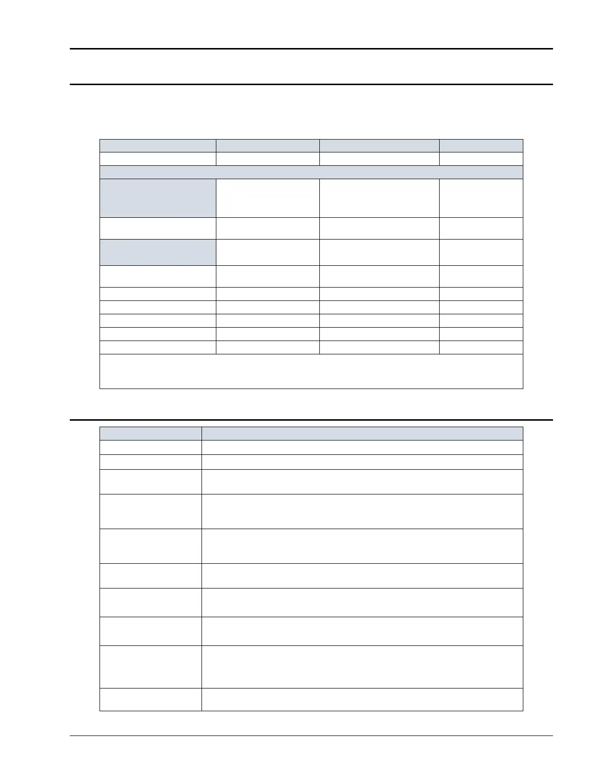
2.1.6 Harmonic Measurements (Pi controller)
Harmonic measurement specifications apply to MX22.5, MX30-3, MX45-3, MX 22.5-
3Pi, MX30-3Pi and MX45-3Pi in three-phase mode. See notes for other models and
configurations.
Frequency fundamental 16.00 - 820 Hz 0.03% + 0.03 Hz 0.01 Hz
MX4 5 -3, MX45-3Pi in 3
phase mode, MX60, MX90,
MX135:
Series I
Series II
32.00 Hz – 6.67 KHz
32.00 Hz – 16 KHz
0.03% + 0.03 Hz 0.01 Hz
MX4 5 -1, MX45-3Pi in 1
phase mode:
Series I
Series II
32.00 Hz - 19.2 KHz
32.00 Hz – 48 KHz
0.03% + 0.03 Hz 0.01 Hz
Phase 0.0 - 360.0° 2° typ. 0.5°
Vo l t a g e Fundamental 0.75V 0.01V
Harmonic 2 - 50 0.75V + 0.3% + 0.3%/kHz 0.01V
Current Fundamental 0.5A 0.1A
Harmonic 2 - 50 0.15A + 0.3% + 0.3%/kHz 0.1A
NOTE: For current measurements, specifications apply from 2% to 100% of measurement range. Current range and accuracy
specifications are times three for MX22.5-1, MX3 0 -1, MX45-1, MX60, MX90 and MX135 or MX30-3Pi / MX45-3Pi in single-
phase mode, respectively.
2.1.7 System Specification
External Modulation:
0 to 10%
Synchronization Input:
Isolated TTL input for external frequency control. Requires 5V at 5 mA for logic high.
Trigger Input:
External trigger source input. Requires TTL level input signal. Triggers on negative edge. Response
time 80 - 100 µs.
Trigger Output:
Programmable through transient list system. 400 µs pulse for voltage or frequency change. Isolated
TTL output. Output reverts to Function strobe when not uses as Trig Out. This function is mutually
exclusive with the Function Strobe output.
Function Strobe:
Active for any voltage or frequency program change. 400 µs pulse for voltage or frequency change.
Isolated TTL output. This function is mutually exclusive with the Trigger Output. Same output is used
for Trigger Output if Trigger Output is programmed as part of list system.
Output Status:
Mo n itors state of the output relay. Isolated TTL output. High if output relay is closed, low if output relay
is open.
Non vol a t il e memory st orage:
Series I: 8 complete instrument setups and transient lists, 32 events per list.
Series II: 16 complete instrument setups and transient lists, 100 events per list.
Wa v e f o r m s
Sine (Models with Standard controller)
Sine, square, clipped, user defined (Models with Pi controller)
Tr a n s i e n t s
Voltage: drop, step, sag, surge, sweep
Frequency: step, sag, surge, sweep
Voltage and Frequency: step, sweep
I EEE-488 Interface:
SH1, AH1, T6, L3, SR1, RL2, DC1, DT1
Syntax: IEEE 488.2 and SCPI