7-4 SPA Assembly Replacement Assembly Replacement
7-4 PN: 10580-00255 Rev. J MT8212E and MT8213E MM
7-4 SPA Assembly Replacement
This section describes the removal of the SPA Assembly board.
1. Open the case as described in Section 7-2 “Opening the Cell Master Case”.
2. Remove the PCB Assembly from the front panel as described in Section 7-3 “PCB Assembly
Replacement”.
3. Remove the castle nuts from the External Reference connector and the External Trigger connector
(Figure 7-5).
4. Remove the motherboard ribbon connector.
5. Remove the 2 MCX connectors between the SPA board and the DSP board.
6. Remove the 6 screws retaining the SPA board.
7. Slide the SPA board out of the top panel.
8. Installation is the reverse of removal.
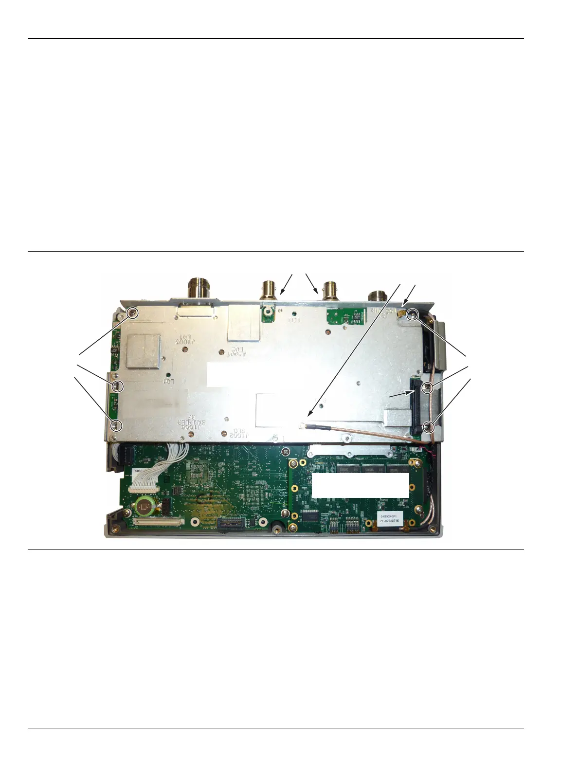
Figure 7-5. Removing the SPA Assemblies
Remove
3 screws
Remove Castle Nuts
Disconnect
Ribbon Cable
Disconnect
MCX Cables
SPA Board
Remove
3 Screws
DSP Board