Instrument Overview 2-6 Test Panel Connector Overview
Cell Master UG PN: 10580-00250 Rev. K 2-9
2-6 Test Panel Connector Overview
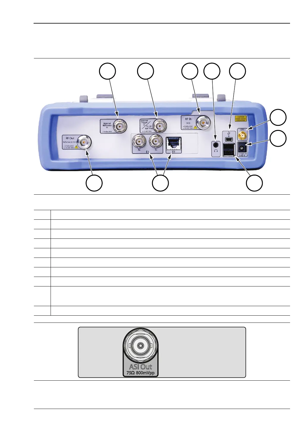
Test panel connectors for the Cell Master are shown in Figure 2-7.
Figure 2-7. Test Panel Connectors
1. External Reference
2. External Trigger, T1 E1 Ref. Freq.
3. RF In (Type N)
4. Headset jack
5. USB Mini-B
6. GPS (Type SMA)
7. External Power
8. USB Type A
9. Option 52: Rx, Tx, E1 Connectors
Option 51 or Option 53: RJ45 is replaced with Bantam Connectors
10. RF Out (Type N)
Figure 2-8. DVB ASI Out BNC Connector for BER Measurements (Option 57 and Option 79)