7-12 Touch Screen Replacement Assembly Replacement
7-12 PN: 10580-00255 Rev. J MT8212E and MT8213E MM
7-12 Touch Screen Replacement
This procedure provides instructions for removing and replacing the touch screen.
1. Open the case as described in Section 7-2 “Opening the Cell Master Case”.
2. Remove the Main VNA/PCB assembly from the front panel as described in Section 7-3 “PCB Assembly
Replacement”.
3. Perform Step 1 through Step 4 of Section 7-9 “LCD Assembly Replacement”.
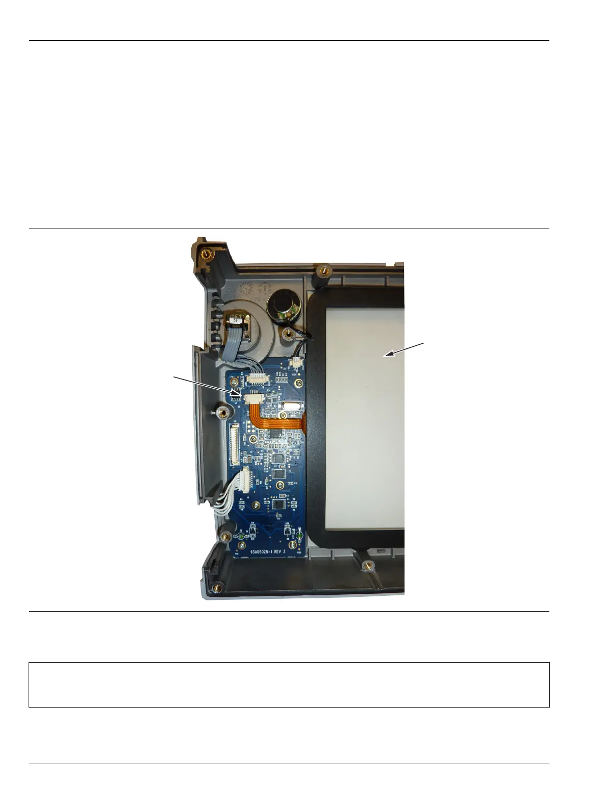
4. Remove the touch screen flex circuit connector from the Keypad PCB by pulling the tabs on each side of
the connector away from the connector and in the direction of the flex circuit. Refer to Figure 7-15.
5. Pull the Touch Screen cable out of the connector housing.
6. Remove the Touch Screen from the Bezel by pulling it straight up.
7. Reverse the above steps to install the replacement Touch Screen.
8. Perform a touch screen calibration by pressing the Shift key and then the 0 key, and follow the on-screen
calibration directions.
Figure 7-15. Replacing the Touch Screen
Note
Firmware version 1.30 and greater was modified to accept touch screen calibration data needed for
touch screen part number ND73867. Ensure that firmware version 1.30 or greater is installed. If not,
install the latest firmware.
Touch Screen
Touch Screen Connector.
Pull down on the Tabs at the
Sides of the Connector
to Remove.