Assembly Replacement 7-3 PCB Assembly Replacement
MT8212E and MT8213E MM PN: 10580-00255 Rev. J 7-3
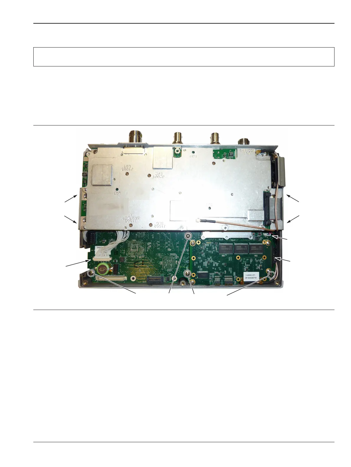
7-3 PCB Assembly Replacement
This section describes the removal and replacement of the SPA and MB/VNA boards which are attached to
each other and attached to the Cell Master Case.
1. Open the case as described in Section 7-2 “Opening the Cell Master Case”.
2. Disconnect the Keypad PCB connector, the Fan Assembly connector, and the LCD connector.
3. Use a Phillips screwdriver to remove the 8 screws securing the Assemblies to the Case (Figure 7-4).
4. After the screws are removed the entire Assembly including the top connector panel will slide out of the
case.
5. Installation is the reverse of removal. During installation ensure the Keypad PCB cable along with all
other cables are properly seated at both ends. Also take care to properly fit the connector panel into the
grooves in the top of the case and confirm that none of the cables will be pinched when the back case is
replaced.
Note
Procedures in this section are generic, and apply to many similar instruments. Photos and
illustrations used are representative and may not match your instrument.
Figure 7-4. Removing the PCB Assemblies out of the Case
Disconnect
Keypad PCB
Cable
Remove
2 screws
on side
Remove
2 screws
on side
Disconnect
Fan Cable
Disconnect
LCD Cable
Remove 4 screws on the Motherboard