Assembly Replacement 7-5 SPA and MB/VNA N Connector Replacement
MT8212E and MT8213E MM PN: 10580-00255 Rev. J 7-5
7-5 SPA and MB/VNA N Connector Replacement
This procedure provides instructions for replacing the N connector attached to the SPA assembly or MB/VNA
assembly.
1. Open the case as described in Section 7-2 “Opening the Cell Master Case”.
2. Remove the PCB Assembly from the front panel as described in Section 7-3 “PCB Assembly
Replacement”.
3. Remove the SPA assembly as described in Section 7-4 “SPA Assembly Replacement”.
4. If removing the MB/VNA N connector, remove the top plate from the MB/VNA.
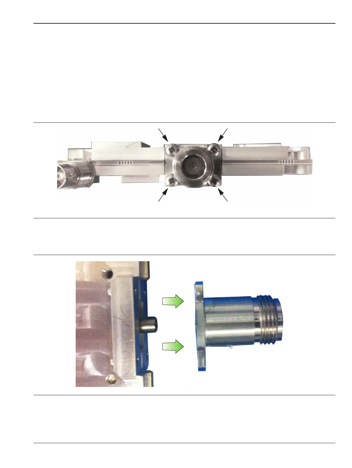
5. Remove the four screws attaching the N connector to the shield (Figure 7-6).
6. Disconnect the N connector from the SPA or MB/VNA by gently pulling the N connector away from the
SPA or MB/VNA (Figure 7-7).
7. Installation is the reverse of removal.
Figure 7-6. Remove 4 Screws
Figure 7-7. Remove N Connector from SPA or MB/VNA