Instrument Overview 2-5 Display Overview
Cell Master UG PN: 10580-00250 Rev. K 2-7
2-5 Display Overview
Figure 2-5 and Figure 2-6 illustrate some of the key information areas of the Cell Master in
Cable & Antenna mode and Spectrum Analyzer mode. For detailed information on either
mode, refer to the Measurement Guides listed in Appendix A, “Measurement Guides”.
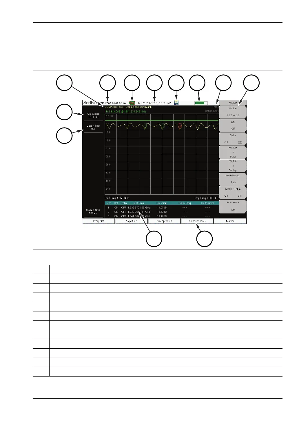
Figure 2-5. Cable & Antenna Analyzer Return Loss Measurement Display
1. Measurement Settings Summary
2. Calibration Status, Type
3. Frequency Standard
4. Date and Time
5. GPS Icon
6. GPS Location
7. Save Icon
8. Battery Charge Indicator
9. Trace Measurement Title
10. Submenu Touch Screen Keys
11. Main Menu Touch Screen Keys
12. Marker Table