Assembly Replacement 7-7 Motherboard/VNA PCB Assembly Replacement
MT8212E and MT8213E MM PN: 10580-00255 Rev. J 7-7
7-7 Motherboard/VNA PCB Assembly Replacement
This procedure provides instructions for removing and replacing the Motherboard/VNA Assembly.
1. Open the case as described in Section 7-2 “Opening the Cell Master Case”.
2. Remove the PCB Assembly from the front panel as described in Section 7-3 “PCB Assembly
Replacement”.
3. Remove the SPA board as described in Section 7-4 “SPA Assembly Replacement”.
4. Remove the GPS board as described in Section 7-6 “GPS (Option 31) Replacement”.
5. Installation is the reverse of removal.
7-8 Fan Assembly Replacement
This procedure provides instructions for removing and replacing the Fan Assembly.
1. Open the case as described in Section 7-2 “Opening the Cell Master Case”.
2. Remove the Main VNA/PCB assembly from the front panel as described in Section 7-3 “PCB Assembly
Replacement”.
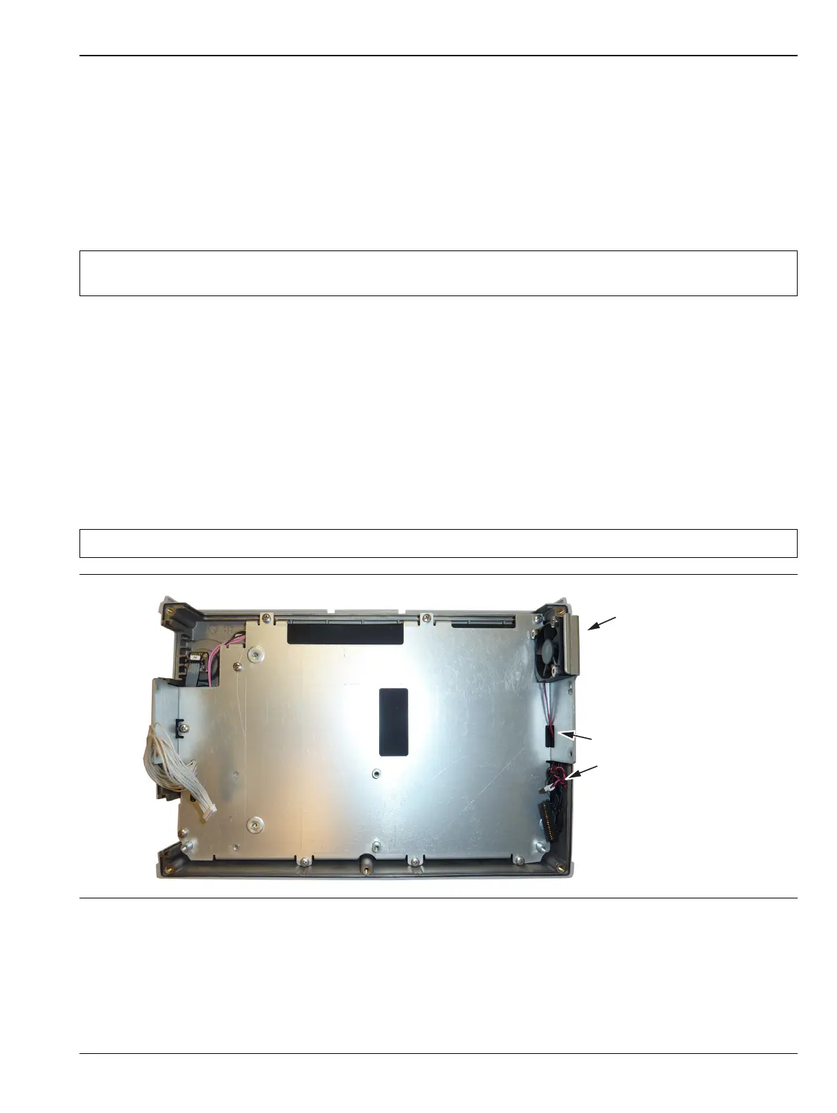
3. Remove the 3 screws and nuts holding the Fan Assembly to the LCD Assembly housing. Refer to
(Figure 7-9).
4. Reverse the above steps to install the replacement Fan Assembly.
Note
When ordering the Main/VNA PCB Assembly all options that areinstalled on the instrument must be
stated on the order.
Note The fan connector cable is routed through the LCD Assembly housing
Figure 7-9. Front Panel Keypad Bezel
Fan Assembly
Fan Connector cables
go though the LCD
Assembly housing