7-2 Opening the Cell Master Case Assembly Replacement
7-2 PN: 10580-00255 Rev. J MT8212E and MT8213E MM
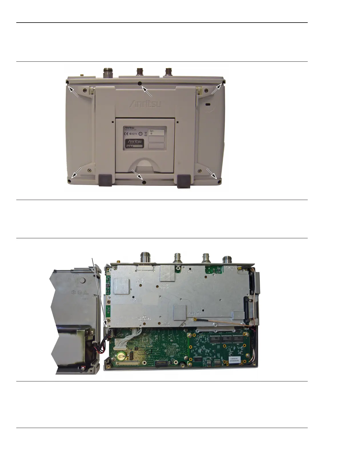
3. Place the Cell Master face down on a stable work surface that will not scratch the display.
4. Use a Phillips screwdriver to remove the six screws securing the two halves of the Cell Master case
together (Figure 7-2).
5. Carefully lift up on the side of the case indicated above and begin to separate the two halves.
6. Lay the Cell Master flat and remove the battery connector cable between the two halves (Figure 7-3).
7. Closing the case is the reverse of opening. Ensure all cables are properly seated and none are pinched
before closing the case.
Figure 7-2. Remove the Four Screws
Figure 7-3. Cell Master Opened 180 Degrees
Carefully lift
this side first
Location of the 6 screws to remove.
Disconnect battery cable to
separate the case halves.