Operation
5-65
5
P/N 6525032M1 - X6
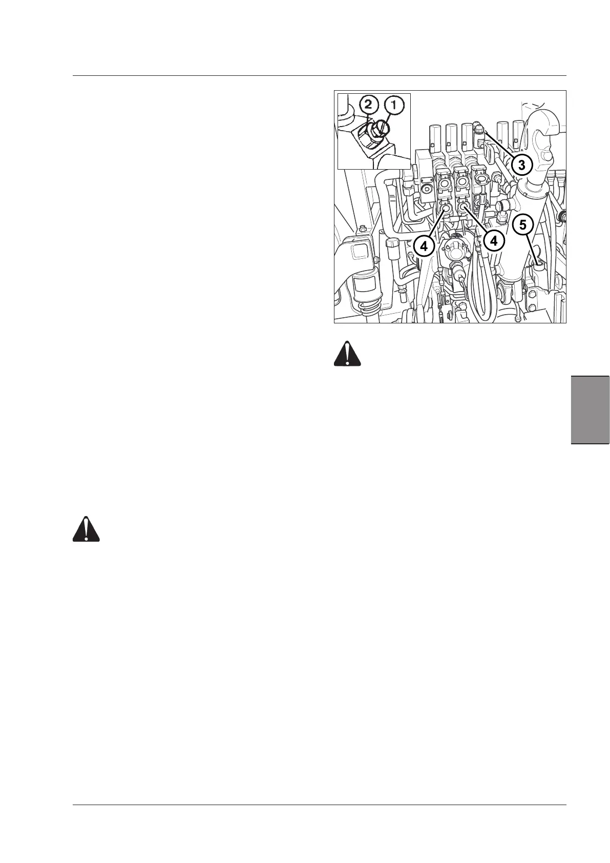
Single/double action selection
(Available only for some types of control valves)
Some types of standard control valve can be adjusted to
control single acting cylinders.
To this purpose, just slacken the check nut (2) and turn
the screw (1) anticlockwise until it stops; then lock the
check nut.
For double acting operation, the screw (1) must be turned
again in a clockwise direction.
Flow divider (if equipped)
A flow divider is available on request (3). It is mounted
on the control valve intake plate and is connected to the
first supplementary control valve that is designed for
use with it.
Flow adjustment
The flow of oil to the first control valve can be regulated.
This device is particularly useful for implements that
require very small amounts of oil to ensure precise adjust-
ment or to regulate the speed of hydraulic motors. It also
makes it possible to maintain a sufficient flow of oil for
use of both the hitch and the external circuit from the first
control valve. Turn the control knob of the flow distributor
to adjust the oil flow.
Quick couplers
Each control valve is equipped with one or two quick-hitch
female half-couplings of the "Push-Pull" type (4), that can
be joined to male half-couplings of any make, as long as
the dimensions are the same. Hitching and unhitching of
the half-couplings are very simple: only push to connect
and pull to detach.
Red - Delivery/Lifting
Yellow - Return/Lowering
WARNING: Discharge all pressure from the
system before hitching or unhitching the
quick couplings.
Remove the dust cap (if fitted). Clean the implement male
coupler before connecting.
Oil spillage collector
Each quick coupling is connected to a tray (5) that col-
lects oil spilt when connecting or disconnecting the quick
couplings. When oil reaches the maximum level in the
collector, this should be emptied into suitable containers
to avoid polluting the environment.
IMPORTANT:DO NOT pour the reservoir contents back
into the hydraulic system. Dispose of contents in accord-
ance with local regulations. DO NOT drain the contents
on the ground or into a drain. Be responsible for the
environment.
WARNING: When using the auxiliary con-
trol valves, quick couplings may reach high
temperatures. Therefore it is mandatory to
use suitable safety gloves when hitching or
unhitching implements connected to these
couplings.
IMPORTANT: When connecting the implement hose to
the tractor, make sure the hose is long enough to permit
the tractor to turn in both directions.
 Loading...