Working with the QATnode STwrench User Guide
278 (326) 9836 4134 01 Edition 2.9
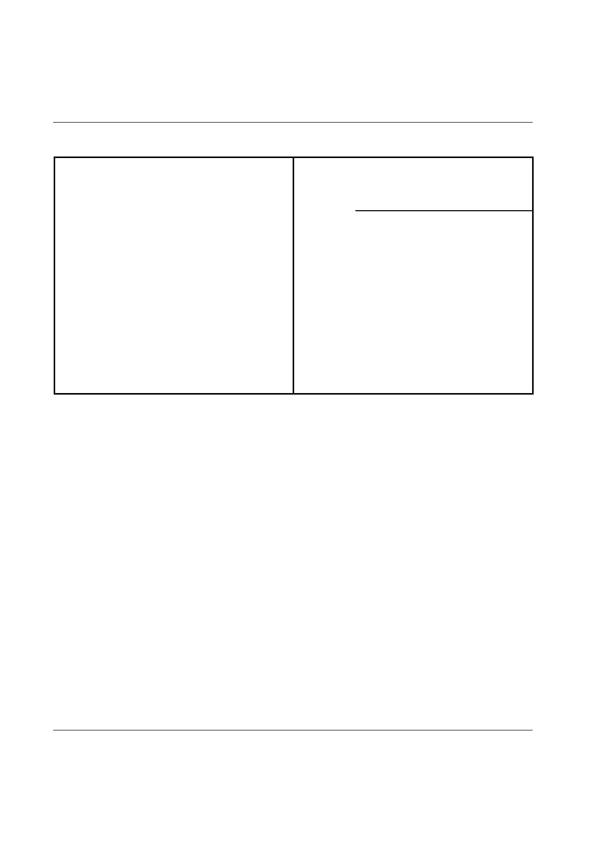
The following table details the I/O connector pinout:
PIN Description PIN Description
1 Common Input GND 9 Common Output
2 Common Input GND 10 Common Output
3 Input 1 + 11 Output 1
4 Input 2 + 12 Output 2
5 Input 3 + 13 Output 3
6 Input 4 + 14 Output 4
7 Input 5 + 15 Output 5
8 Input 6 + 16 Not connected
To activate the input 1, provide a 12 VDC ÷ 24 VDC between the “Input 1 +”and the “Common Input
GND“; the input current required by the input is a maximum of 20 mA.
The five outputs are relays, with a common pole “Common Output”. The outputs can work up to +24
VDC, with 1 A maximum current.
The inputs and outputs status is shown by the LEDs on the QATnode.
Here is an example of a connection, in which six switches are used to command the inputs and five lamps
are use to monitor the output status:
 Loading...