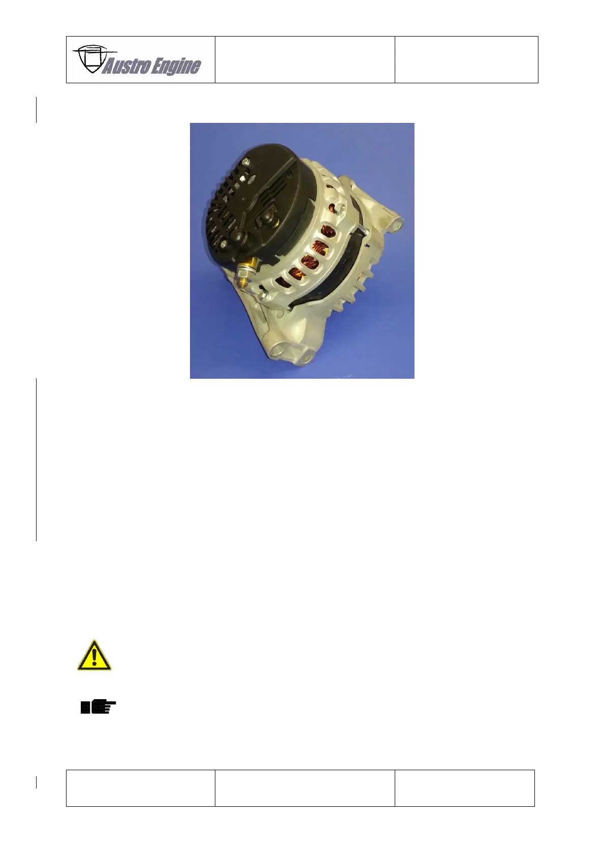
24-31-00 Alternator E4A-91-400-000
Fig. 24 - 24 Alternator E4A-91-400-000
24-31-10 Removal of Alternator E4A-91-400-000
1. Disconnect the battery according to the applicable Aircraft Maintenance Manual.
2. Remove the power line from the B+ terminal according to the applicable Aircraft
Maintenance Manual.
3. Remove the electrical line marked with “GEN/G2”. The lock nut [6] and the plastic
cover lock nut [7] will be needed for installation again. Remove the screws [2] and
[4].
4. Remove the drive belt - refer to Chapter 85-40-11.
24-31-20 Installation of the Alternator E4A-91-400-000
1. Carefully install the Alternator [5] and install the mounting screws [4].
2. Torque the screws [2] and [4] with 20 Nm.
3. Connect the electrical cable marked with “GEN/G2”. The fastening torque for the lock
[6] nut is 2,7 Nm – 3,8 nm. Make sure that the black plastic cover [6] is placed on the
lock nut. Connect the power line to the B+ terminal (fastening torque 11-13 Nm). Put
the white dust seal [8] of the electrical cable over the black plastic cover of the lock
nut.
If the connection is wrong a serious damage to engine is possible.
4. Install the drive belt according to Chapter 85-40-12.
Inspect the drive belt for correct installation.
5. Connect the main battery according to the applicable Aircraft Maintenance Manual.