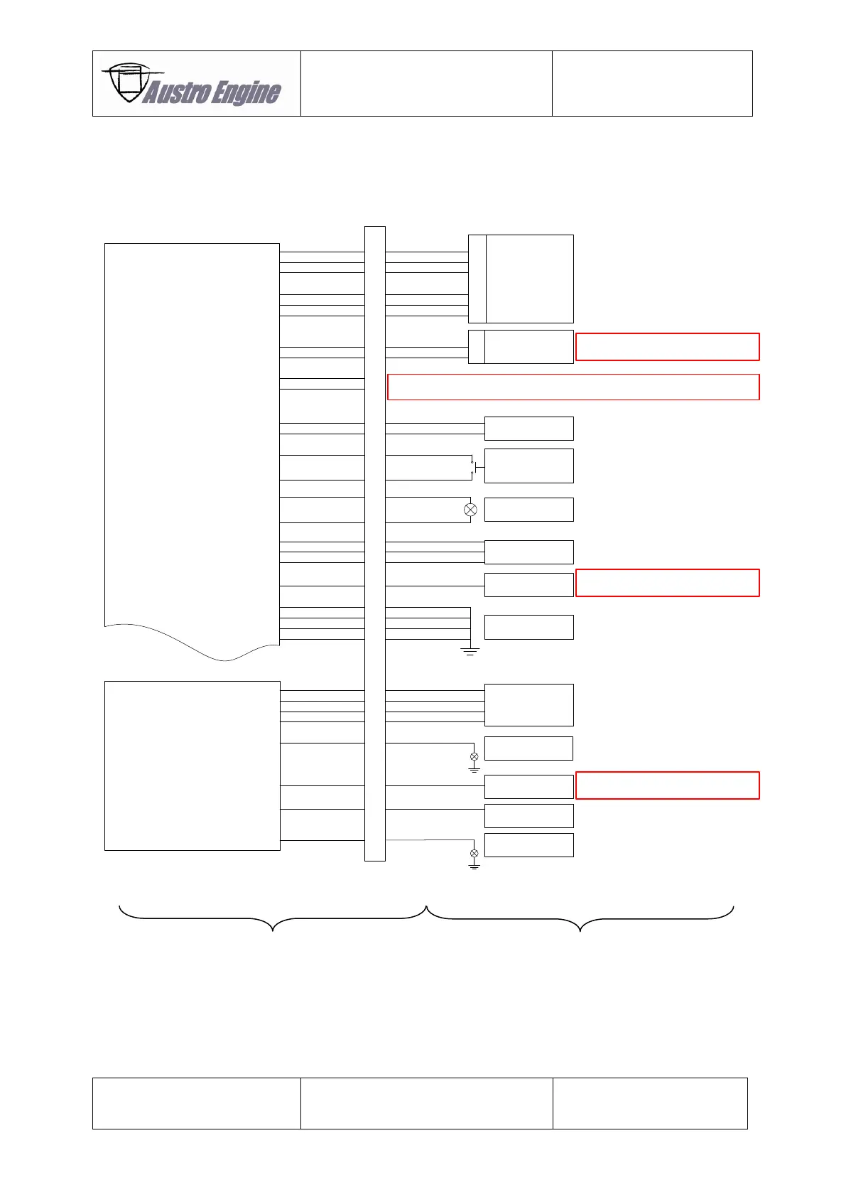
GPC
A/C Interface
1
5
6
2
4
3
7
8
9
10
11
12
13
14
15
16
17
18
19
20
21
22
23
24
25
26
27
28
29
30
31
32
CPC connector 1
Pin
Power Lever
Sensor
ECU A
Pin
1
4
2
6
3
5
Pin
2
7
Display and
Diagnostic Interface
Connect to display unit and provide separate
SUB D (RS232) connector (female)
Currently not used
Engine Master
ECU A
Engine Selftest
Pushbutton
(normally open)
Caution Lamp
ECU A
CAN BUS Interface 1
28V Power Supply
ECU A
A/C on ground
indication
Ensures that selftest is only performed when
A/C is on ground
28V Power Supply
GPC
A/C on ground
indication
Ensures that GPC is only active when A/C is
on ground
GND Power Supply
ECU A
Glow Enable
Announcement Lamp
GPC
Caution Lamp
GPC
EECU
CAN BUS Interface 2
Sensor Supply
Sensor Signal
Sensor GND
CAN L
CAN H
CAN L
CAN H
Engine Master
Engine Master
Selftest Signal
Selftest GND
Caution Lamp Supply
Caution Lamp Signal
ECU A Power Supply
ECU A Power Supply
ECU A Power Supply
ECU A GND Supply
ECU A GND Supply
ECU A GND Supply
ECU A GND Supply
Signal A/C on ground indication
Sensor Supply
Sensor Signal
Sensor GND
GPC Announcement Lamp
GPC Power Supply
GPC Power Supply
GPC Power Supply
GPC Power Supply
Signal A/C on ground indication
Glow Enable
GPC Caution Lamp
Fig. 92 - 5