EasyManuals Logo

Austro Engine AE330 User Manual

Default Icon
360 pages
To Next Page IconTo Next Page
To Previous Page IconTo Previous Page
Page #201 background imageLoading...
Page #201 background image
Maintenance Manual
E4.08.04
Issue date: 14-Apr-2015
Page: 71-65
Revision no: 25
Step 5:
Connect the single wires of the repair kit E4A-95-
R12-000 with the remaining engine wiring
harness as shown in the table below using the
inline crimps and crimp tool.
Check the correct pinning of the sensor cable
branch which has been repaired.
CTS_GPC:
CTS:
FTS:
GBTS:
Connector
Pin
Connector
Pin
GPC
21
CTS_GPC
1
GPC
20
CTS_GPC
2
Connector
Pin
Connector
Pin
ECU A
x
CTS
1
ECU A
w
CTS
2
Connector
Pin
Connector
Pin
ECU B
x
FTS
1
ECU B
w
FTS
2
Connector
Pin
Connector
Pin
ECU A
v
GBTS
1
ECU A
u
GBTS
2
Step 6:
Move the blue isolation sleeve over the inline crimps and
heat them with a hot air gun (300 °C).
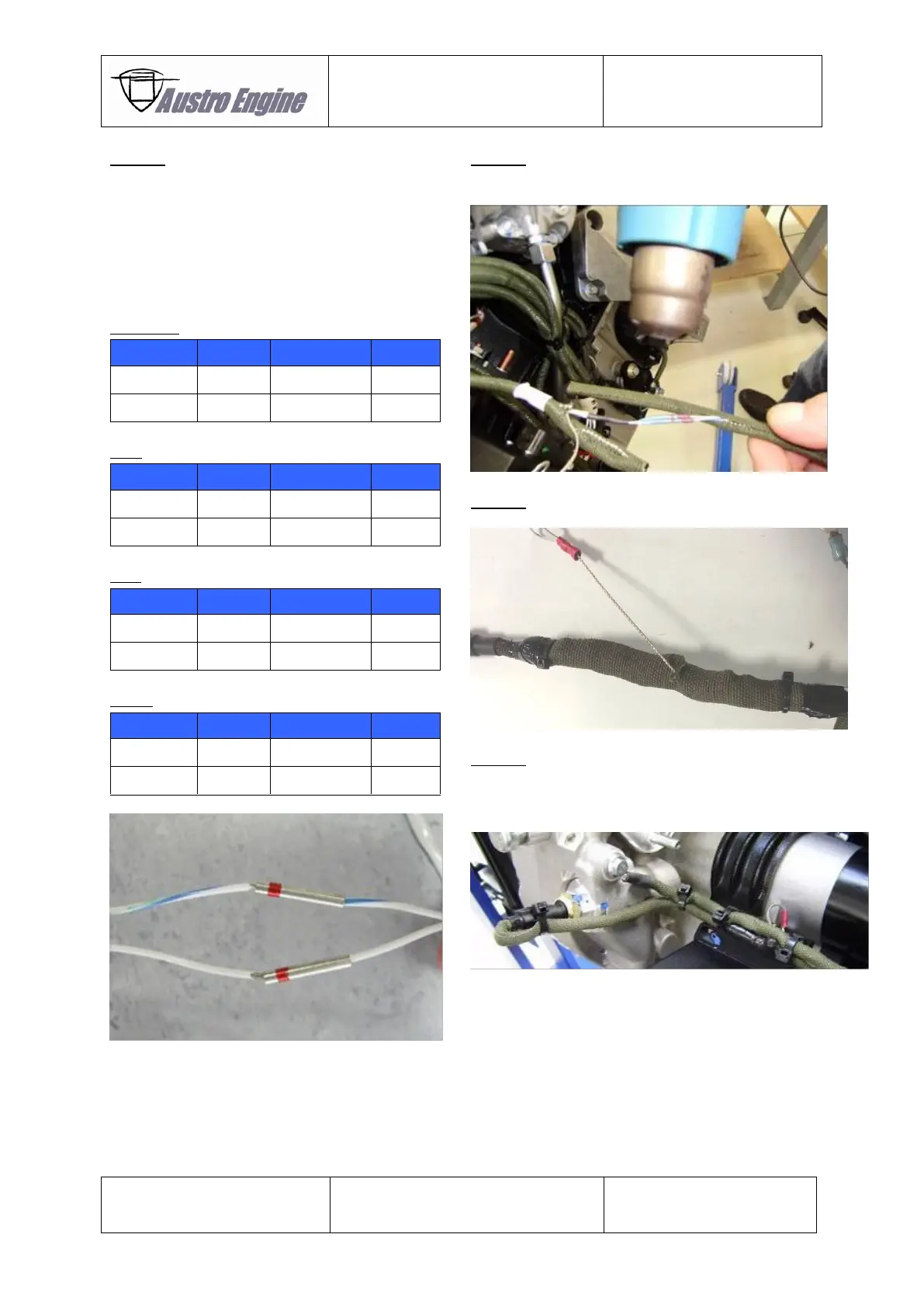
Step 7:
Put the ROUNDIT over the cable as shown below.
Step 8:
The cable ties and the fusion tape can be used for fixation
ROUNDIT and the cable harness (sample shown below for
the GBTS).

Table of Contents

Questions and Answers:

Question and Answer IconNeed help?

Do you have a question about the Austro Engine AE330 and is the answer not in the manual?

Austro Engine AE330 Specifications

General IconGeneral
BrandAustro Engine
ModelAE330
CategoryEngine
LanguageEnglish

Related product manuals