EasyManuals Logo

Austro Engine AE330 User Manual

Default Icon
360 pages
To Next Page IconTo Next Page
To Previous Page IconTo Previous Page
Page #48 background imageLoading...
Page #48 background image
Maintenance Manual
E4.08.04
Issue date: 14-Apr-2015
Page: 01-22
Revision no: 25
01-10-60 Electrical System Description
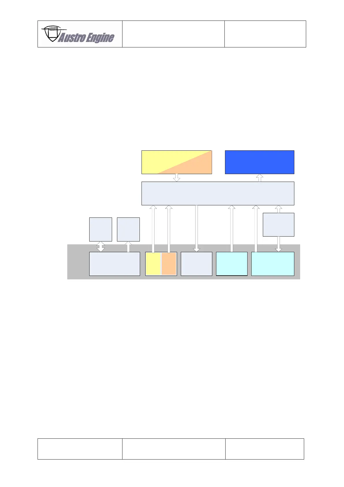
The Electrical System consists of the following major Components:
– Starter
– Generator
– GPC – Glow Plug Control Unit
– EECU – Electronic Engine Control Unit
– Sensors & Actuators
The EECS Block Diagram shows the connection between the EECS components which are used in the
AE 300 Engine and displays also the Interface from the Airframe to the EECS of the AE 300.
Fig. 01 - 15 EECS Block Diagram
EECU
Actuators
Glow
Plug
Control
Starter
Generator
A/C
EECS
Engine
Monitoring
System
3way Cockpit
Switch
A/C PowerA/C Interface
Engine Sensors
Power
Lever
Control
signals

Table of Contents

Questions and Answers:

Question and Answer IconNeed help?

Do you have a question about the Austro Engine AE330 and is the answer not in the manual?

Austro Engine AE330 Specifications

General IconGeneral
BrandAustro Engine
ModelAE330
CategoryEngine
LanguageEnglish

Related product manuals