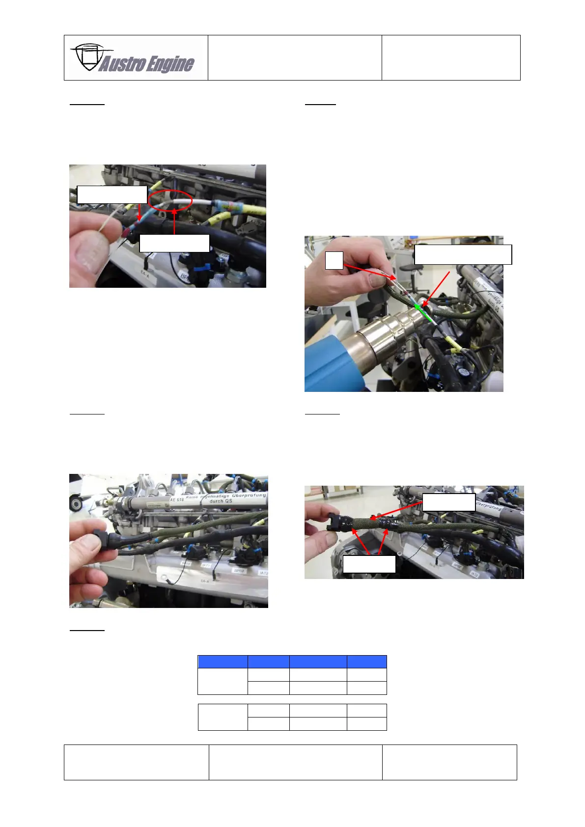
Step 5:
Strip the insulation behind the inline crimp (5mm
± 2mm) which was mounted as described in
Step 4.
Ensure not to cut off the shielding below the
insulation.
Move the solder sleeve, which was putted over the
wire of the reaming harness (see Step 3), over the
shielding that was exposed at step 5. The red
marking of the solder sleeve should be placed over
the exposed shielding.
Put the white / black wire (3) of repair kit cable E4A-
90-R16-000 into the solder sleeve (expose wire
should connect the shielding).
Heat the solder sleeve (300°C – 350°C) with a hot
air gun until the solder sleeve is connected with the
cable and the shielding.
Put the smaller ROUNDIT over the cable as shown
below. The cable ties or / and the tape of the
repair kit can be used for fixation of the ROUNDIT
as necessary.
The bigger ROUNDIT can be placed in addition over
the smaller ROUNDIT for improved chafing
protection.
The cable ties or / and the tape of the repair kit can
be used for fixation of the ROUNDIT as necessary.
Step 9:
Check with a Multimeter the connection between the pins as stated below: