Step 5:
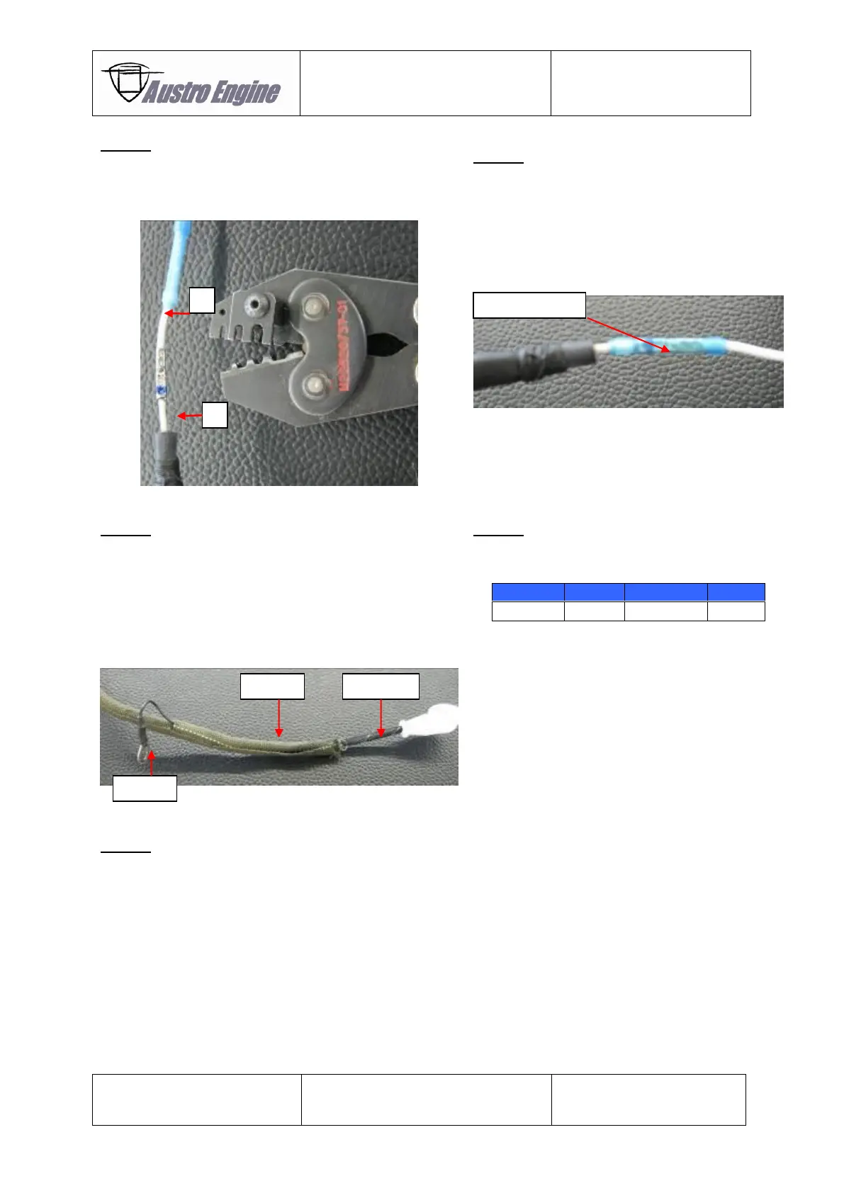
Use the crimp tool Mil Standard Part Number:
M22520/37-01 to connect the repair kit cable (A) and
the remaining engine harness (B).
Step 6:
Put the blue isolation sleeve of the inline crimp
D-436-37 directly over the splice crimp.
Heat the inline crimp isolation sleeve (300°C –
350°C) with a “hot air gun” until the inline crimp
isolation seals the inline crimp barrel and the
single wires.
If necessary the green roundit 2000NX5-5 which is part
of the repair kit can be put over inline crimp and the
black expando of the repair kit cable.
If the green roundit of the remaining harness is long
enough to cover the inline crimp and the black expando
this step will not be needed.
Ensure that the pig tail is not covered by the roundit.
Use a Multimeter to check connection between
the pins stated below:
Cable ties PLT1M-M30 and PLT4S-M30 can be used for
fixation of repair kit cable.