Display and Diagnostic Interface:
The Display and diagnostic interface is a High Speed CAN Bus (with 500k Baud) which is used to
transmit all information to a display/indication panel.
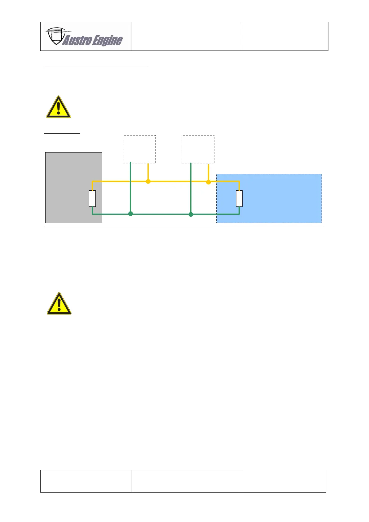
A BUS termination is required at the physical end of the BUS.
CAN-termination resistors 60R (2x 120R in parallel, 120R in EECU included)
(CAN Bus according to ISO 11898)
For Example:
CAN Termination in
Installation
120R
EECU
120R
CAN
nodes
CAN
nodes
CAN Low
CAN High
CAN
termination
Fig. 01 - 21 CAN Bus Termination
Make sure that the terminating connector is installed in a save position that in any event a
disconnection is impossible.
According to the CAN BUS Protocol each ECU of the EECU sends its own engine information.
Any device connected to the EECU CAN BUS must not transmit any data on the EECU CAN BUS!
It is part of the installer’s responsibility to verify that the information displayed in the
engine instruments conform to the information provided by the CAN BUS.