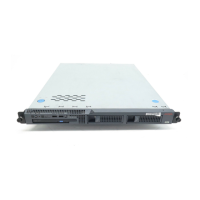
Replacing the S8500 server
03-300529 Issue 4 January 2008 33
Figure 5: S8500 rear panel
Confirming the original Ethernet configuration (S8500)
After the server is back in service, check the original Ethernet configuration settings.
1. Go to the Configure Server Web page.
2. Confirm that the server’s Ethernet configuration settings are the same as before.
Preparing the failed server for shipment
The following steps prepare the server for return shipment to Avaya:
1. Insert the new hard drive from the replacement server into the drive cage so that the
connectors are in the same direction as the CD-ROM connectors and the screws holes are
aligned (see Figure 2: Removing and replacing the drive cage (S8500) on page 26
).
2. Reinsert the four screws (two on each side) to attach the hard drive to the drive cage.
3. Reattach the flat ribbon cable (in two places) to the hard drive and CD-ROM drive.
4. Reattach the two power cables to the hard drive and CD-ROM drive.
5. Slide the drive cage into place making sure that it fits securely into the retaining hooks and
finger-tighten the captive screw.
Figure notes:
1. External power-supply connector for
RSA
2. Power LED for RSA
3. Error LED for RSA
4. Serial connector for RSA modem
5. Ethernet RJ45 connector on RSA
6. 9-pin RS232 connector
7. Services port
8. Connection to customer network
9. Video port (not used)
10. Mouse connector (not used)
11. Keyboard connector (not used)
12. System error LED
13. Power-on LED
14. Optional dual network interface card
(NIC)
1 2
LINK TX/RX LINK TX/RX
PCI
1
PCI 2
100-127 -, 3,0A, 50/60 Hz
200-240 -, 1,5A, 50/60 Hz
133 MHz/64 Bit, 100 MHz/64 Bit
7
2 4 5
6
8912
h3msble3 LAO 102804
1
3
13 11 10
14

 Loading...