7-58
Chapter 7. PARAMETER SETUP
[Resistor type]
WhendrivinganSSRbyvoltagetime-proportionaloutput,theout-
putvoltageofthecontrollermustbewithintheinputratedvoltage
(optimumignitionvoltage)oftheSSR.
OntheDCP31,anewlydevelopedvariableoutputsystemisutilized
thatenablesoutputoftheoptimumignitionvoltageevenwhendriv-
ingtwoormoreSSRs.
Thissystemsetstheoptimumcurrentvalueonthecontrollersothat
theoptimumignitionvoltagewithrespecttotheinternalimped-
anceoftheSSRsidecanbeobtained.
Thefollowingshowsequivalentcircuitsandrelatedformulas:
•DescriptionofSymbols
(1) Details
I
O
:Settingoutputcurrentofcontroller(settingrange:2
to22mA)
V
O
:Maximumappliedloadvoltage(approx.14.7V)
V
SSR’
:ActualinputvoltagetoSSR
V
SSR
:InputratedvoltagerangeofSSR(V
SSR/MIN
to
V
SSR/MAX
)
V
SSR/MIN
:MinimuminputratedvoltageofSSR
V
SSR/MAX
:MaximuminputratedvoltageofSSR
Z :InternalimpedanceofSSR
V
D
:InternalvoltagedropofSSR(normally1to2V)
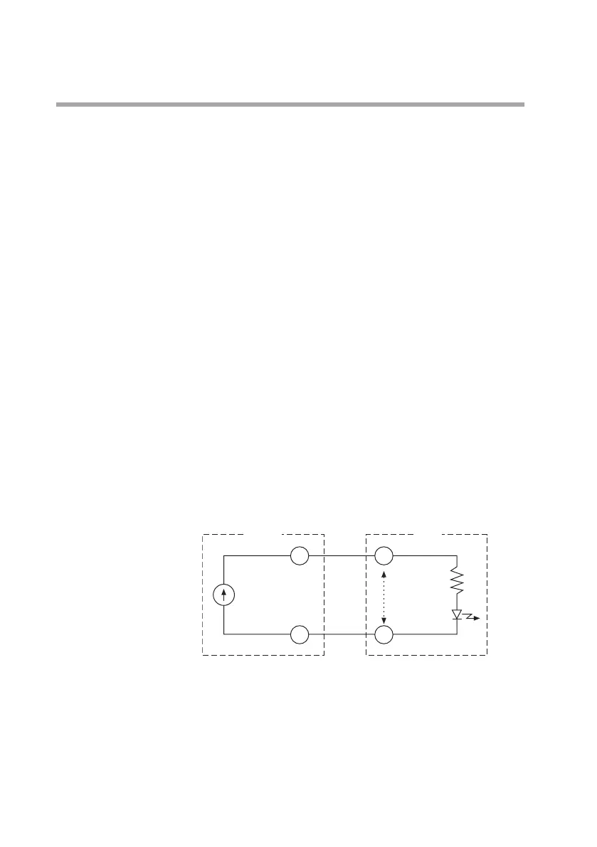
(2)EquivalentcircuitwhenoneSSRisconnected
Formulas(1)and(2)formulasmustbesatisfied.
(1)formula V
SSR/MIN
≤I
O
×Z+V
D
≤V
O
(2)formula V
SSR'
<V
SSR/MAX
(V
SSR'
=I
O
×Z+V
D
)
+
–
+
–
I
O
(V
O
)
V
SSR'
Z
V
D