514
Maintenance / Servicing • Installing the UPS module
Automation PC 620 with 945GME N270 CPU board User's Manual V 1.10
4. Installing the UPS module
The module is installed using the materials included in the delivery. Different parts are used
depending on the system unit and whether the add-on interface module is installed (description
starting on page 523) or not installed (description follows).
4.1 Automation PC 620 without add-on interface module
4.1.1 APC620, 1 PCI slot
• Remove side cover (see section 5 "Mounting the side cover", on page 531).
• Remove UPS module cover by removing the 2 marked Torx screws (T10).
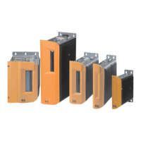
Figure 274: Add-on UPS module 5AC600.UPSI-00 - Installation materials
Figure 275: Remove UPS module cover
Connection cable
Mounting bracket
Spacing bolt (14 mm)
Spacing bolt (16 mm)
Torx screws (T10)
Spacing ring (2 mm)
 Loading...