Chopper units and braking resistors
Manual b maXX
®
BM1000
Document No. 5.07003.04 Baumüller Nürnberg GmbH
126
of 174
B.1
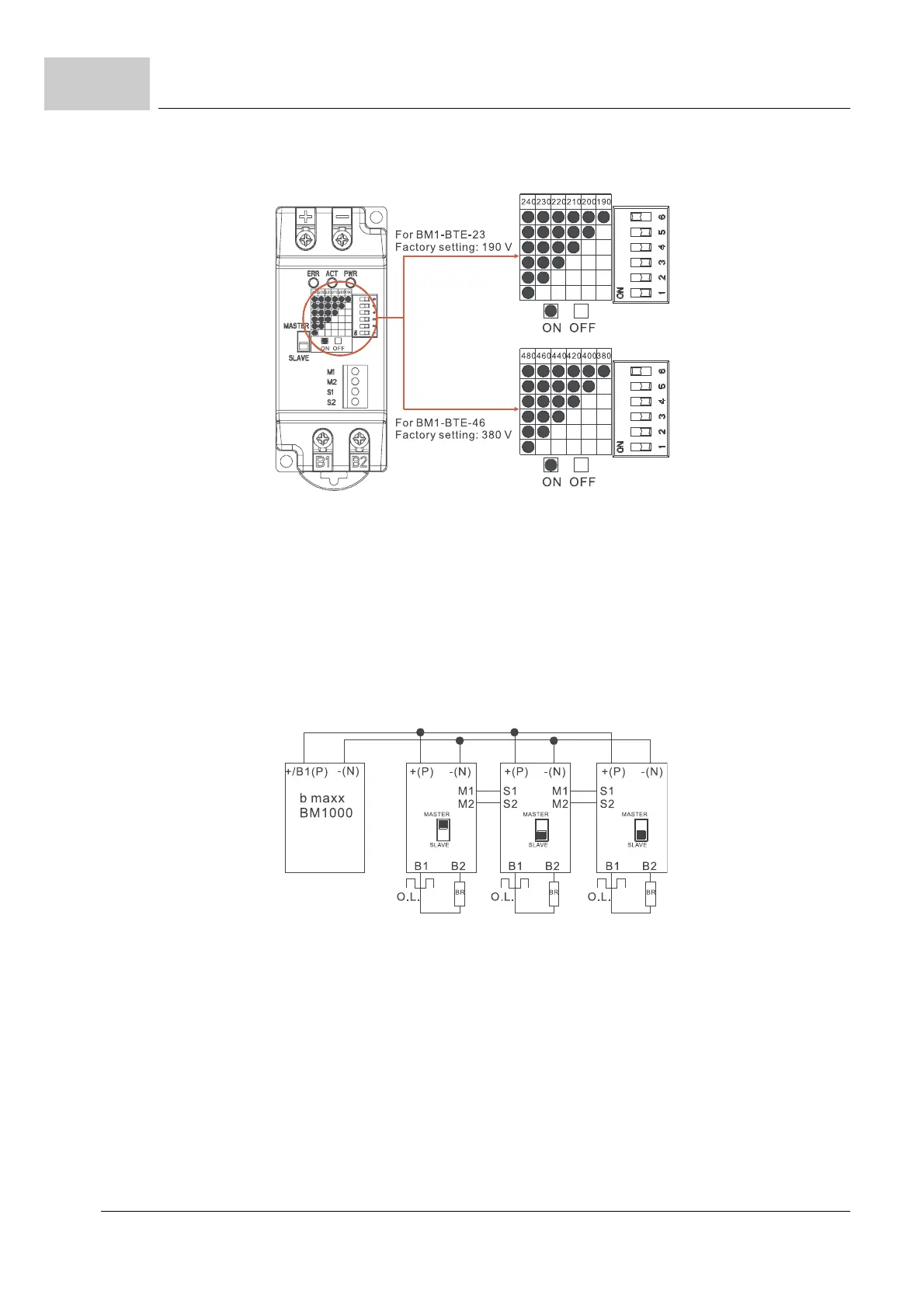
Figure 67: Voltage setting chopper unit
m Master/Slave setting
The MASTER/SLAVE jumper is set „MASTER“ as factory setting. The „SLAVE“ setting
is applied to two or more chopper units in parallel, making these chopper units be en
-
abled/disabled synchronously. Then the power dissipation of each unit will be equiva-
lent so that they can perform the braking function completely.
n Wiring example
The SLAVE braking application of three chopper units is shown. After wiring, the
jumper of first unit shall be set as „MASTER“ and that of others must be set as
„SLAVE“ to complete the system installation.
Figure 68: Wiring example Master/Slave setting



 To Next Page