Control Terminals
Manual b maXX
®
BM1000
Document No. 5.07003.04 Baumüller Nürnberg GmbH
64
of 174
6.11
Keep control wiring as far away as possible from the power wiring and in separate con-
duits to avoid interference. If necessary let them cross only at 90º angle.
The device control wiring should be properly installed and not touch any live power wir-
ing or terminals.
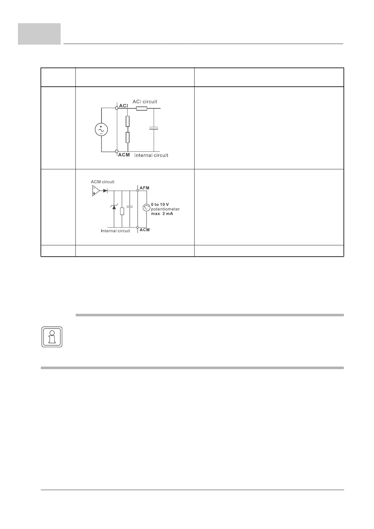
ACI Analog current input
Figure 35: Analog current input
Impedance: 250 Ω
Resolution: 10 bits
Range: 4 to 20 mA =
0 to max. output frequency (P0033)
Selection: P0801, P0809, P1359
Set-up: P1128 to P1132
AFM Analog output meter
Figure 36: Analog output meter
0 to 10 V, 2 mA
Impedance: 20 kΩ
Output current 2 mA max.
Resolution: 8 bits
Range: 0 to 10 V
DC
Function: P1162 and P1163
ACM Analog control signal (ground) Ground for AVI, ACI, AFM
Terminal
symbol
Terminal function Factory settings (NPN mode)
ON: connect to DCM
NOTE
If a filter is required for reducing EMI (Electro Magnetic Interference), install it as close as
possible to the device. EMI can also be reduced by lowering the carrier frequency.
When using a GFCI (Ground Fault Circuit Interrupter), select a current sensor with sensi-
tivity of 200 mA, and not less than 0.1-second detection time to avoid noise tripping.