Mounting
Manual b maXX
®
BM1000
Document No. 5.07003.04
39
of 174
5
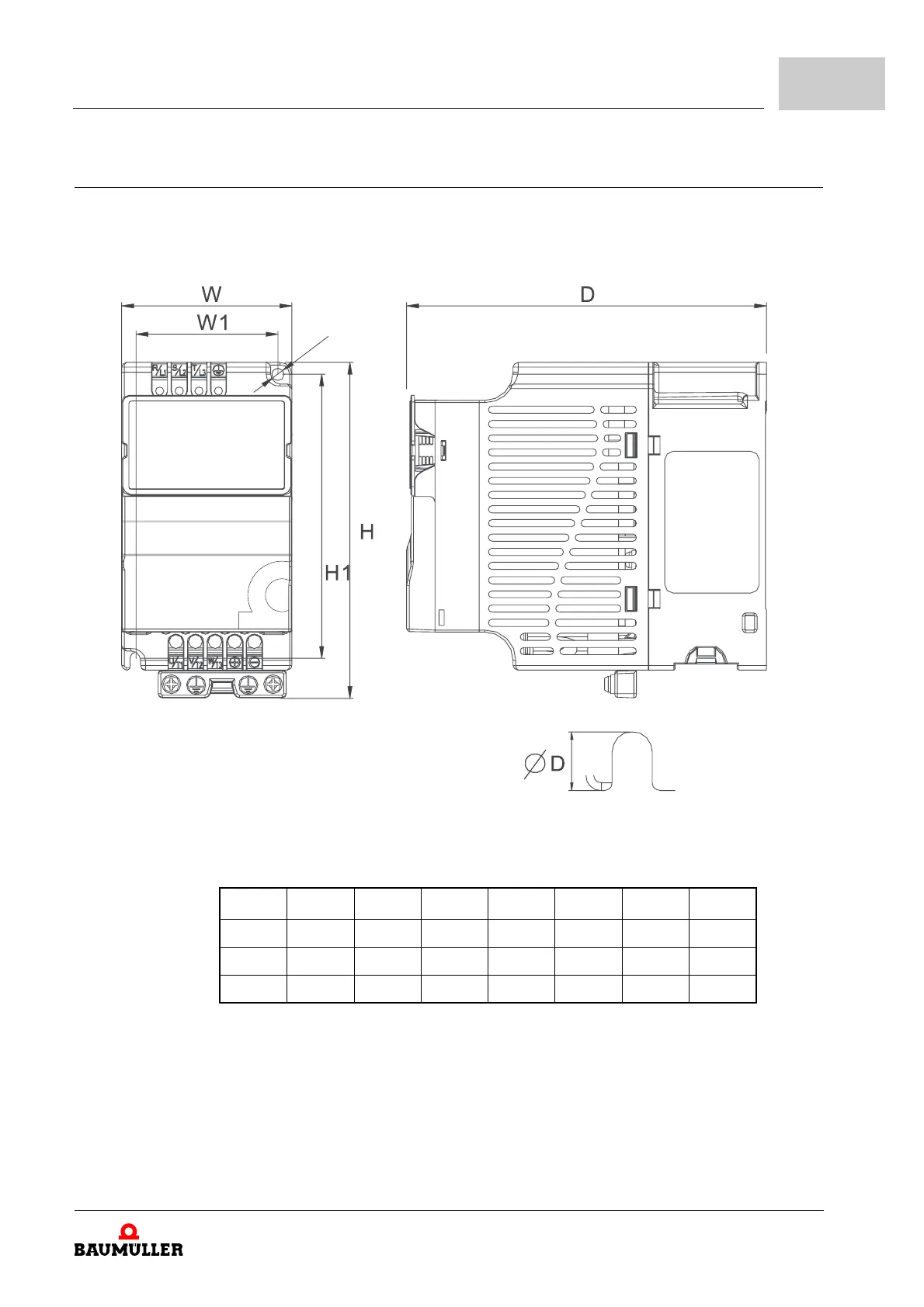
5.5 Dimensions
The following drawings show the dimensions of the devices. Use these drawings, to pre-
pare the necessary drilling/cut-outs. Use the drawings under ZInstallation space– from
page 36, to determine the required space in the control cabinet.
Figure 18: Dimensions
Frame W W1 H H1 D
∅ D∅
1 72.0 60.0 142.0 120.0 152.0 5.2 7.6
2 100.0 89.0 174.0 162.0 152.0 5.5 9.3
3 130.0 116.0 260.0 246.5 169.0 5.5 9.8