Installation
Manual b maXX
®
BM1000
Document No. 5.07003.04
63
of 174
6
6.11.2 Terminal symbols and functions
Terminal
symbol
Terminal function Factory settings (NPN mode)
ON: connect to DCM
MI1 Forward-Stop command ON: Run in MI1 direction
OFF: Stop according to stop method
MI2 Reverse-Stop command ON: Run in MI2 direction
OFF: Stop according to stop method
MI3 Multi-function input 3 Refer to P1091 to P1094 for programming the multi-
function Inputs.
ON: the activation current is 16mA.
OFF: leakage current tolerance is 10µA.
MI4 Multi-function input 4
MI5 Multi-function input 5
MI6 Multi-function input 6 Fix value for pulse (controller) enable
+24V DC voltage source +24V
DC
, 20 mA used for PNP mode.
DCM Digital signal ground Ground for digital inputs and used for NPN mode.
RA Multi-function relay output (N.O.) a Resistive Load:
5A (N.O.) / 3A (N.C.) 240 V
AC
5A (N.O.) / 3A (N.C.) 24 V
DC
Inductive Load:
1.5A (N.O.) / 0.5A (N.C.) 240 V
AC
1.5A (N.O.) / 0.5A (N.C.) 24 V
DC
Refer to P1110 for programming
RB Multi-function relay output (N.C.) b
RC Multi-function relay ground
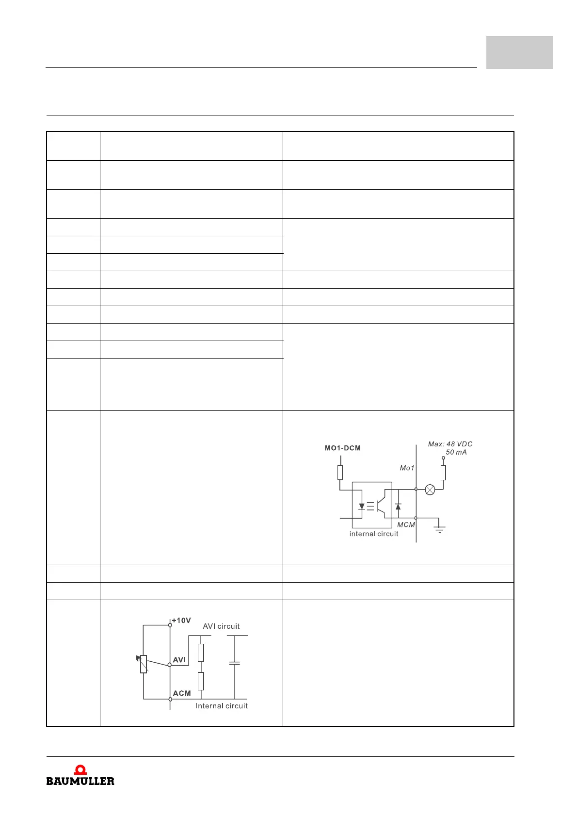
MO1 Multi-function output 1 (photocoupler) Maximum 48 V
DC
, 50 mA
Refer to P1111 for programming
Figure 33: Multi-function output 1
MCM Multi-function output ground Ground for multi-function outputs
+10V Potentiometer power supply +10V
DC
3 mA
AVI Analog voltage input
Figure 34: Analog voltage input
Impedance: 47 kΩ
Resolution: 10 bits
Range: 0 to 10 V
DC
=
0 to max. output frequency (P0033)
Selection: P0801, P0809, P1359
Set-up: P1128 to P1132