Installation
Manual b maXX
®
BM1000
Document No. 5.07003.04
57
of 174
6
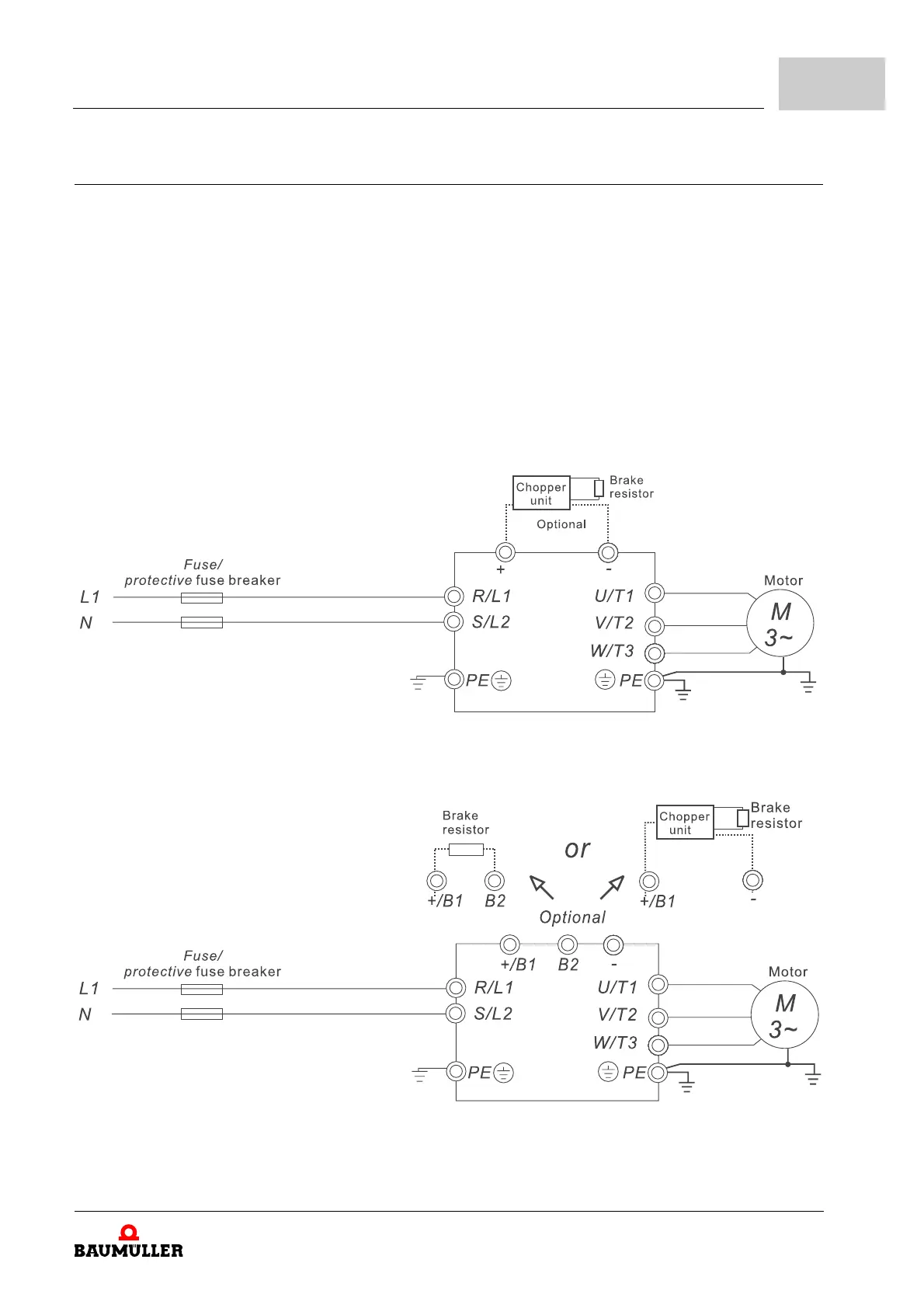
6.10.2 Connecting main terminals
m Frame 1 (BM1211, BM1212, BM1213, BM1412, BM1413, BM1414):
No built-in chopper unit:
Optional use of chopper unit and braking resistor necessary (refer to ZB.1.2 Chopper
units BM1-BTE– from page 121 and ZB.1.3 Dimensions and weights for braking
resistors– from page 127).
m Frame 2 and 3 (BM1224, BM1225, BM1425, BM1426, BM1437, BM1438, BM1439):
Built-in chopper unit:
Optional connection of a suitable braking resistor (see ZB.1.3 Dimensions and
weights for braking resistors– from page 127) possible.
If the motor generates additional regeneration energy a further chopper unit with brak-
ing resistor can be connected.
m BM1211, BM1212, BM1213 (Frame 1)
Figure 26: Mains terminals connections 1
m BM1224, BM1225 (Frame 2)
Figure 27: Mains terminals connections 2