80-0000010B OM
101
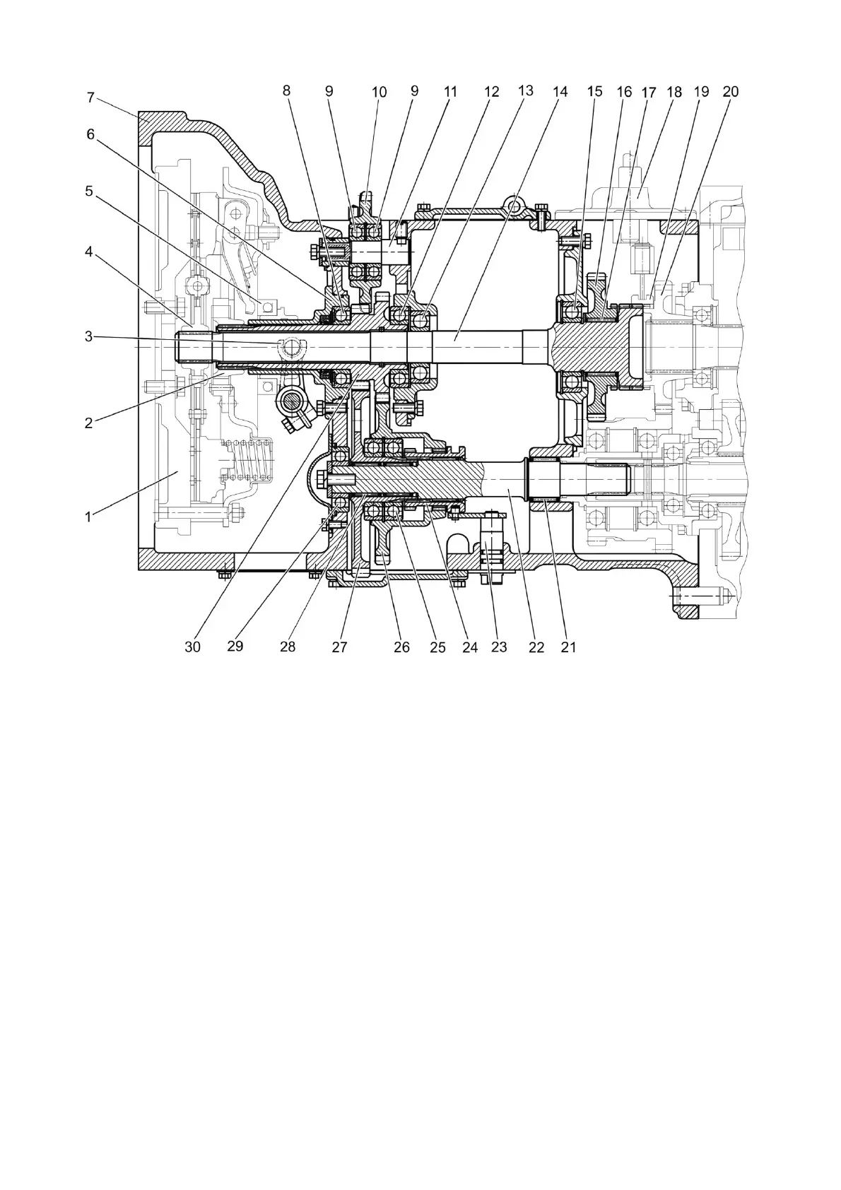
1 – flywheel; 2 – floating bushing; 3 – fork; 4 – hub; 5 – release bearing; 6 – shifter
bracket; 7 – clutch casing; 8, 9, 12, 13, 15, 25, 29 – bearing; 10 – gear of the HLL pump drive;
11 – axis; 14 – output shaft; 16 – drive gear of the gear reduction unit; 17 – rollers; 18 – gear
reduction unit control mechanism; 19 – gear coupling; 20 – driven gear of the gear reduction
unit; 21, 28 – needle bearing with outer casing; 22 – driven shaft of PTO drive; 23 – control
shaft; 24 – gear coupling; 26 – driven gear of PTO drive (1000 min
-1)
mode); 27 – driven gear of
PTO drive (540 min
-1)
mode); 30 – drive gear shaft of PTO drive.
Figure 3.2.5 – Clutch casing with mechanical gear reduction unit
Reverse-reduction gear (figure 3.2.6) is intended for changing the direction of trac-
tor travel. The reverse-reduction gear is located between the clutch casing and the gear-
box. Synchronizer 18 is located on the gearbox primary shaft. The synchronizer carriage,
controlled by mechanism 17, can get engaged with driven gear of the reverse-reduction
gear 19 (reverse movement) or with drive gear of the reverse-reduction gear 16 (forward
movement). The reverse-reduction gear lever is brought into the tractor cabin. When you
shift the lever forward in the direction of tractor travel forward movement engages. When
you shift the lever backwards reverse movement engages.