80-0000010B OM
102
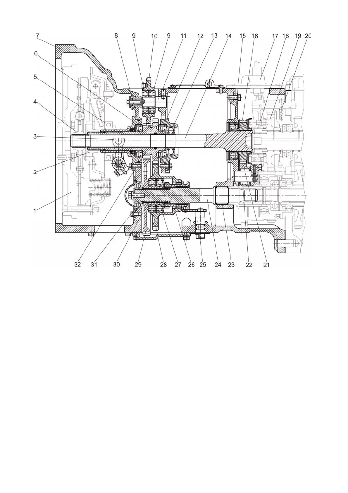
1 – flywheel; 2 – floating bushing; 3 – fork; 4 – bushing; 5 – release bearing;
6 – shifter bracket; 7 – clutch casing; 8, 9, 12, 13, 15, 27, 31 – bearing;
10 – gear of hydraulic system pump drive; 11 – axis; 14 – output shaft; 16 – drive gear of
reverse-reduction gear; 17 – reverse-reduction gear control mechanism; 18 – synchro-
nizer; 19 – driven gear of reverse-reduction gear; 20 – small ball;
21 – idler gear of reverse-reduction gear; 22 – needle bearing;
23, 30 – needle bearing with outer cage; 24 – driven shaft of PTO drive; 25 – control shaft;
26 – gear coupling; 28 – driven gear of PTO drive (1000 rpm mode); 29 – driven gear of
PTO drive (540 rpm mode); 32 – drive gear shaft of PTO drive.
Figure 3.2.6 – Clutch casing with reverse-reduction gear
The synchronized gear reduction unit (figure 3.2.7) is intended for getting additional
number of speeds, necessary for operation with agricultural machines. The speed reduc-
tion unit is located between the clutch casing and the gearbox. On the primary shaft of the
gearbox synchronizer 18 is installed. Synchronizer carriage, which is controlled by control
mechanism 17, can get engaged with driven gear of the gear reduction unit 19 (step-down
gearing of the gear reduction unit) or with drive gear of the gear reduction unit 16 (step-up
gearing of the gear reduction unit). The shift lever of the synchronized gear reduction unit
is brought into the tractor cabin.