80-0000010B OM
228
ATTENTION: AS PRESSURE IN THE TANK GOES UP TO 0.77 MPA, THE COM-
PRESSOR IS SWITCHED TO IDLE RUNNING BY THE PRESSURE REGULATOR AND
TYRE INFLATION STOPS AUTOMATICALLY. FOR THIS REASON, CHECK THE PRES-
SURE OVER THE INDICATOR ON THE DASHBOARD FROM TIME TO TIME AND, IF
NECESSARY, REDUCE IT THROUGH THE CONDENSATE REMOVING VALVE!
On tractors without trailer brakes’ drive installed, tyres are inflated through the tyre
inflation valve, which is located on the pneumatic compressor.
Inflate the tyres through the tyre inflation valve as follows:
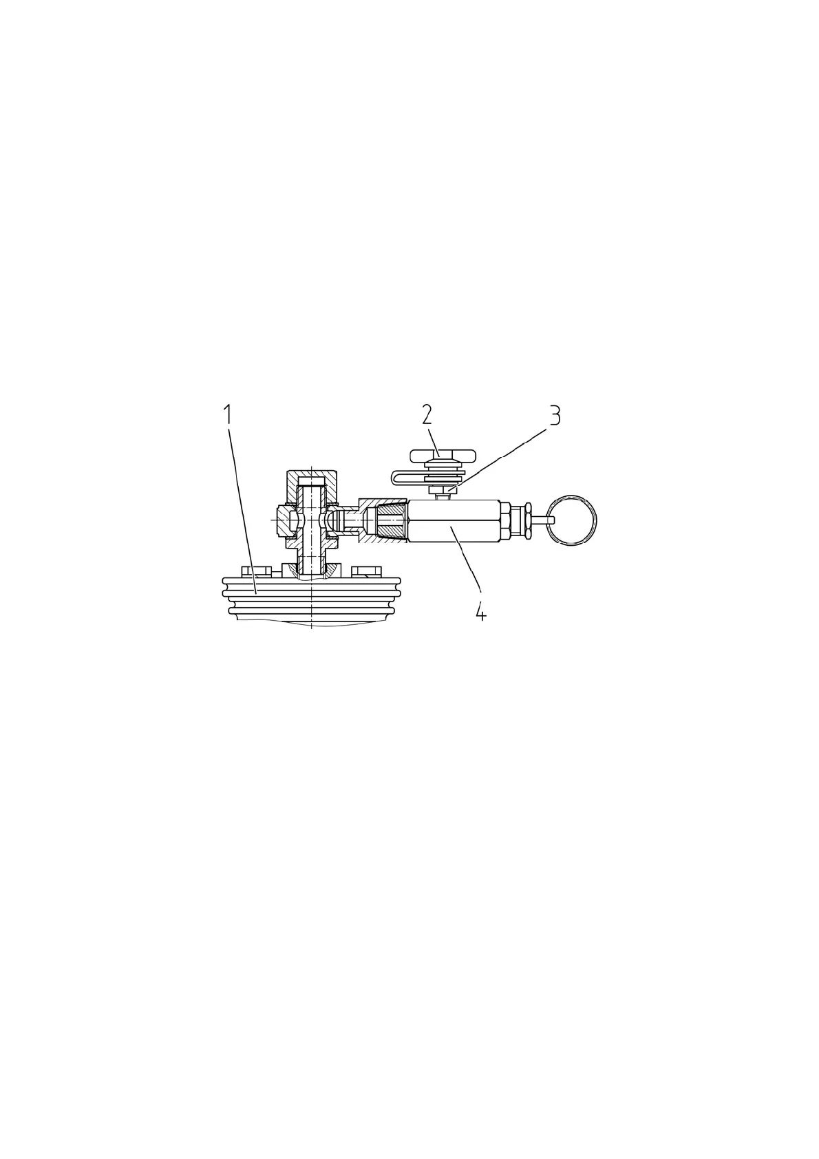
- unscrew winged nut or remove cap 2 (figure 4.2.3) of fitting 3;
- connect a hose to inflate tyres to air bleeding fitting 3 and to tyre valve;
- turn on the pneumatic compressor 1 and inflate the tyre to reach the necessary
pressure, while controlling it with a tyre manometer;
- detach the hose from the tyre valve and from the air bleed fitting;
- turn off the pneumatic compressor 1 and screw in the winged nut or install cap 2
onto fitting 3 of the tyre inflation valve 4.
1 – pneumatic compressor; 2 – winged nut or cap; 3 – fitting; 4 – tyre inflation valve.
Figure 4.2.3 – Tyre inflation valve assembly