80-0000010B OM
237
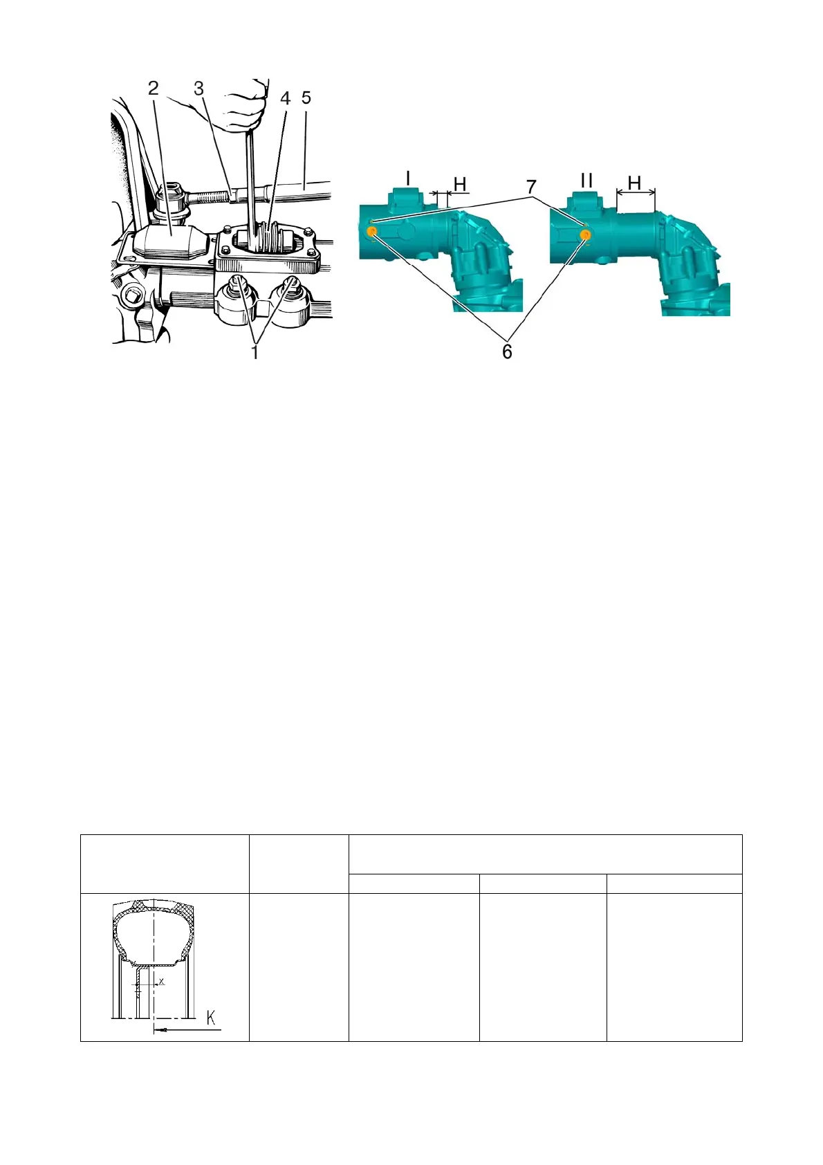
1 – wedges; 2 – cover of adjusting screw; 3 – nut; 4 – adjusting screw 5 – steering
link tube; 6 – lock-pin; 7 – split pin.
Figure 4.2.15 – Method of front wheel track change on tractor with FDA 72-2300020-
А-04 mounted
To set the necessary track by means of re-placing the wheels from one sideboard to
the other, do the following operations:
- brake the tractor using the parking brake. Put wheel chocks at the front and back of
rear wheels;
- jack up the front part of the tractor (or the front wheels, one by one) to provide clear-
ance between the wheels and the ground;
- to form the track, undo the nuts fastening the wheel plate to reduction unit flange,
remove the wheels and re-place to the other sideboard;
- when mounting the wheels, make sure that the direction of wheel rotation coincides
with the direction of the arrow on the tyre sidewall;
Tighten the nuts attaching the wheel to reduction unit flange with a torque of 200 to
250 Nꞏm.
Diagrams for track formation and track sizes for tyres 11.2-20 (basic configuration for
tractor BELARUS-82.1 with FDA 72-2300020-А-04) are given in table 4.2.8.
Table 4.2.8 – Changing front wheel track of tractor with FDA 72-2300020-А-04
mounted
Wheel mounting dia-
gram
Plate offset
X, mm
Tractor track К, mm (tyre 11.2-20) (when HSC cylinder is
attached to holes 1, 2, 3 (figure 4.2.14))
hole 1 hole 2 hole 3
+80
1400
(Dimension
А=270)
1510
1)
(Dimension
А=325)
1620
(Dimension А
=380)