80-0000010B OM
300
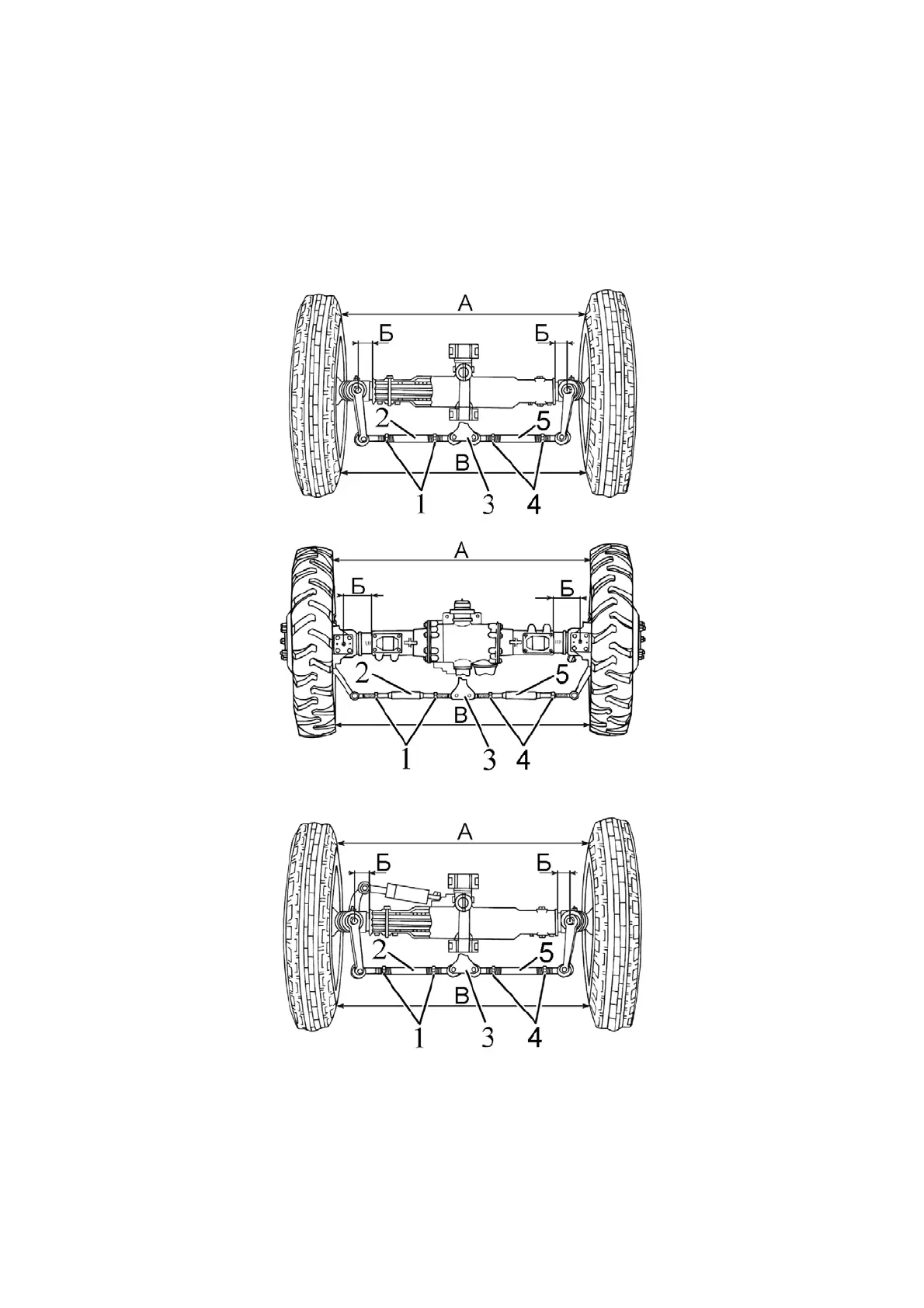
b) by rotating steering link tubes 2 and 5 (extend or shorten the right and lest link
by identical length), make the value (“C”-“A”) fit into range from 0 to 8 mm and gauge
stick 2 (figure 3.13.2) be immersed to the max. into the body of differential lock sensor;
c) repeat operations, described in subparagraphs 5 and 6;
d) if value (“C”-“A”) (Figure 6.4.18) falls within the limits of 0 to 8 mm and gauge
stick 2 (figure 3.13.2) is immersed to the max. into the body of differential lock sensor, then
tighten steering link lock nuts 1 and 4 (Figure 6.4.18) with torque of 100 to 140 Nꞏm, leav-
ing steering link length unchanged
a) for tractors with non-driving front axle (with HPS)
b) for tractors with FDA (with bevel wheel gear groups, with HPS)
c) for tractors with non-driving front axle (with HSC and HPS body)
1, 4 – locknuts; 2 – adjusting tubes of steering links, 3 – drop arm.
Figure 6.4.18 – Diagram of front wheels’ toe-in adjustment