80-0000010B OM
53
Handwheel of correction speed control 4 serves for adjustment of agricultural im-
plement position correction speed during tractor operation. When handwheel 4 is rotated
clockwise the correction speed decreases, when rotated anticlockwise it increases. Carry
out adjustment of handwheel 4 after you finish adjusting the RLL and mounted implements
(plough, tiller etc.).
When preparing implement for work with the use of draft control method proceed as
follows:
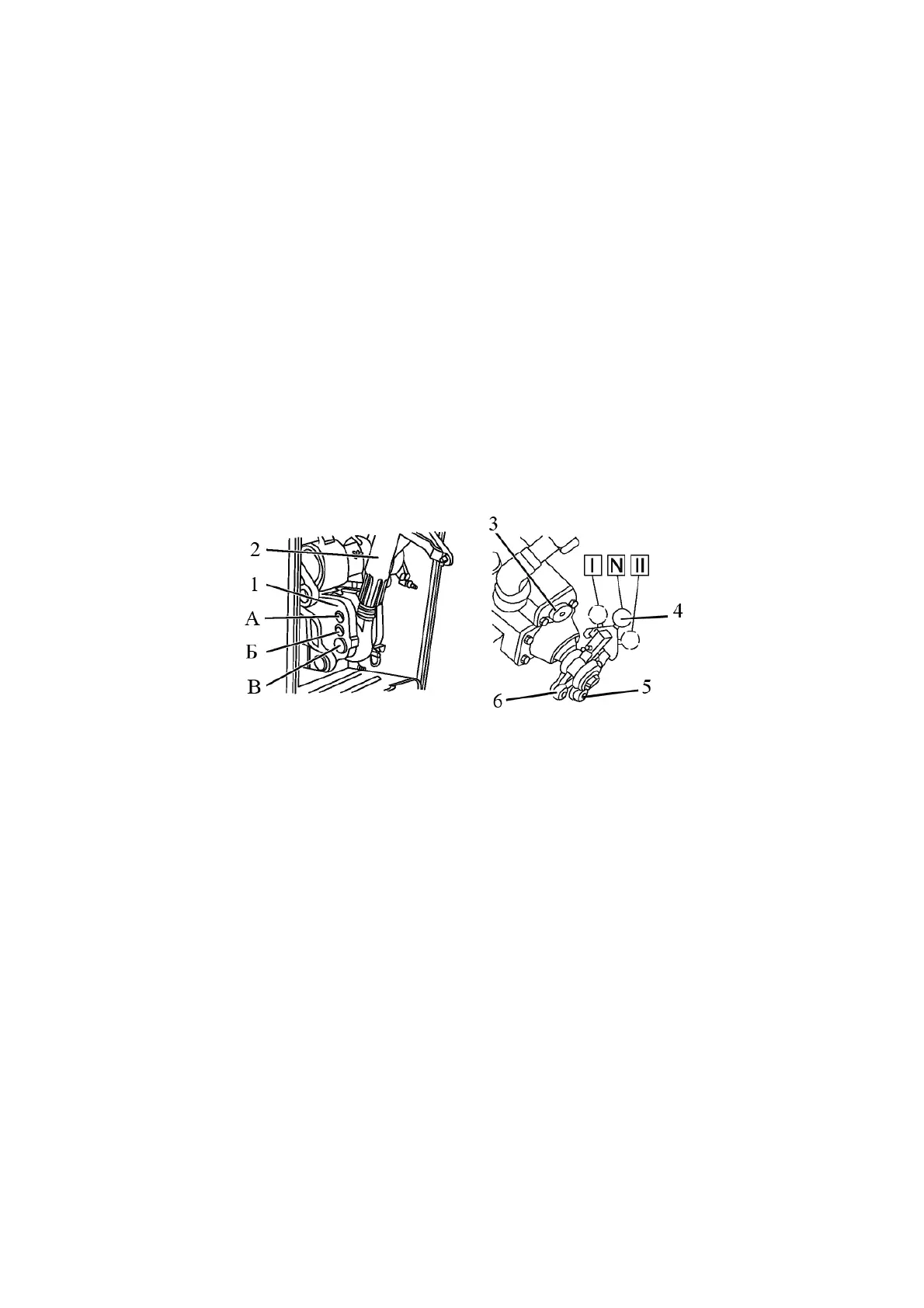
- mount upper link 2 (figure 2.17.2) of the lift linkage on the upper hole of clevis 1
(position “A” in figure 2.17.2);
- attach the mounted implement (machine) to the tractor RLL;
- if necessary carry out adjustments of the RLL and mounted implements.
- switch on draft control method, for doing this raise the mounted implement (ma-
chine) in the upper most position and get switch 4 into the groove of draft lever 5 by turn-
ing switch to the left (along the tractor) to position “II”. For easier switching before getting
into the groove, shift the switch forward (along the tractor) until it is aligned with the groove
on lever 5;
- adjust handwheel of correction speed control 3. When the handwheel is rotated
clockwise the correction speed decreases, when rotated anticlockwise it increases. Turning
the handwheel, achieve smooth automatic adjustment of depth during operation. Do not turn in
the handwheel clockwise against the stop, because it will lead to excessively slow lifting of the
implement (machine) and will cause increased slipping of the tractor drive wheels.
1 – clevis; 2 – upper link; 3 – handwheel of correction speed control; 4 – control
method switch; 5 – groove of draft lever; 6 – groove of position lever.
Figure 2.17.2 – Position of control switch and upper link when draft control is used
At the start of the run of cultivated land lower mounted implement, by turning handle
2 (figure 2.17.1) forward. The further forward the handle is set, the greater depth of tillage
will be. When you shift handle 2 towards yourself the depth will decrease. After adjusting
to the desired depth, shift stroke limiter 1 along the groove of the control console until it
stops against the handle and lock it.
At the end of the run of cultivated land to raise the implement set handle 2 to the
position “lifting” – towards yourself until it stops. After lifting the handle has to automatically
return to the neutral position “N”.
At the start of each subsequent run lower the implement by shifting handle 2 forward un-
til it stops against stroke limiter 1.
While working on ploughing in cases, when draft control handle is set forward for
the maximum depth, the obtained depth is insufficient, mount again upper link 2 of the mounted
implement on the middle hole of clevis 1 (position “Б” in figure 2.17.2);
When you mount upper link, adjust handwheel of correction speed and select the hole
in the clevis for specific soil conditions and each type of agricultural implements. No readjust-
ments are required during operation.