125
THIS IS AN UNCONTROLLED DOCUMENT.
THIS ELECTRONIC DOCUMENT MAY HAVE BEEN SUPERCEDED.
THE MOST CURRENT DOCUMENT INFORMATION IS AVAILABLE
FROM YOUR BELL HELICOPTER TEXTRON REPRESENTATIVE.
PRODUCT DATA JANUARY 2003
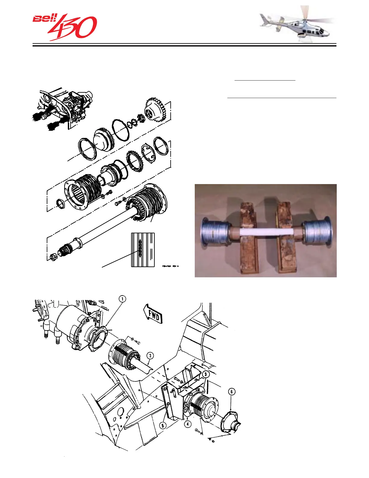
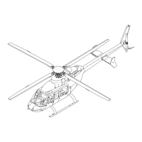
MAIN DRIVESHAFT INSTALLATION
1. Outboard Quill Adapter
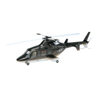
2. Main Driveshaft
3. C-shaped Half (upper)
4. C-shaped Half (lower)
5. Quick Disconnect
6. Engine Output Adapter
OVERTEMPERATURE INDICATORS
Power is supplied to the transmission
through two
main drive shafts. Each shaft
has a flexible splined coupling at either
end, which
allows for variations in alignment
caused by normal motions of the
transmission. The dynamically balanced
shafts pass through the forward firewall
inside quick-disconnect baffle assemblies
which maintain the required isolation of the
engine compartment. Overtemperature
indicators are found on each coupling, and
will change color if the coupling has
exceeded operational limits.
POWER TRAIN
MAIN DRIVE SHAFTS