74
THIS IS AN UNCONTROLLED DOCUMENT.
THIS ELECTRONIC DOCUMENT MAY HAVE BEEN SUPERCEDED.
THE MOST CURRENT DOCUMENT INFORMATION IS AVAILABLE
FROM YOUR BELL HELICOPTER TEXTRON REPRESENTATIVE.
PRODUCT DATA JANUARY 2003
POWER DISTRIBUTION
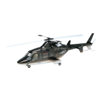
STARTER GENERATOR NO.2
Electrical power is distributed by two independent subsystems, which may be
interconnected in the event of a generator failure. System protection is accomplished
with relays, circuit breakers, fuses, and isolation diodes. In normal operation, each
generator supplies 28 VDC power, controlled by individual fault sensing voltage
regulators, to a DC bus, and an EMERGENCY bus. Items considered ESSENTIAL for
flight are connected to the
emergency buses, while items NONESSENTIAL for flight
are connected to the
DC buses. Loss of either generator will cause the loss of its' DC
bus, but not the loss of its'
emergency bus, which is interconnected to the opposite
emergency bus. The failed DC bus may have power restored by activating the bus
interconnect relay (BUS INTCON switch).
FAULT PROTECTION
The bus interconnect relay is inhibited from
closing if a bus / feeder fault (short circuit)
exists. This is to prevent connection of the
operative generator to a faulty circuit.
Diodes prevent reverse current flow from
the emergency buses to the failed DC bus.
The emergency buses are fault protected
from each other by two EMER BUS PWR
circuit breakers, while the DC buses are
guarded from ground faults in an
emergency bus by two 40 amp fuses.
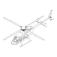
VOLTAGE REGULATOR
Each starter-generator is controlled by a
separate solid state voltage regulator,
located in the aft electrical compartment.
They monitor generator output voltage,
control the generator relays, energize the
DC GEN warning lights, and monitor shunt
voltage for fault protection and to prevent
overcurrent.
•EXAMPLE•