80
THIS IS AN UNCONTROLLED DOCUMENT.
THIS ELECTRONIC DOCUMENT MAY HAVE BEEN SUPERCEDED.
THE MOST CURRENT DOCUMENT INFORMATION IS AVAILABLE
FROM YOUR BELL HELICOPTER TEXTRON REPRESENTATIVE.
PRODUCT DATA JANUARY 2003
Provision is made for the defog nozzles
connection to heated air ducts from the
optional Environmental Control System,
when installed.
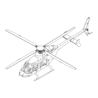
Additional cockpit ventilation is provided
from two overhead outlets which receive
air from the cabin ventilation system.
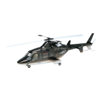
The two cable assembly control knobs
located above and below each vent nozzle
control the plenum door and the diverter
valve. Pressing the center of each knob
and sliding the cable out or in varies the
door opening (upper knob), or diverts
airflow (lower knob) to the defog nozzle.
Releasing the center of the knob locks the
cables position. The vent nozzles, located
on either side of the instrument panel may
be adjusted for direction and volume. Each
system will function with ram air only, or
for ground / hovering operation, with the
vent blowers (PILOT VENT BLO & CPLT
VENT BLO switches on the overhead
console).
CREW VENTILATION / WINDSHIELD DEFOGGING
Two separate systems, pilot and forward
passenger position, provide for crew
ventilation and windshield defogging. Each
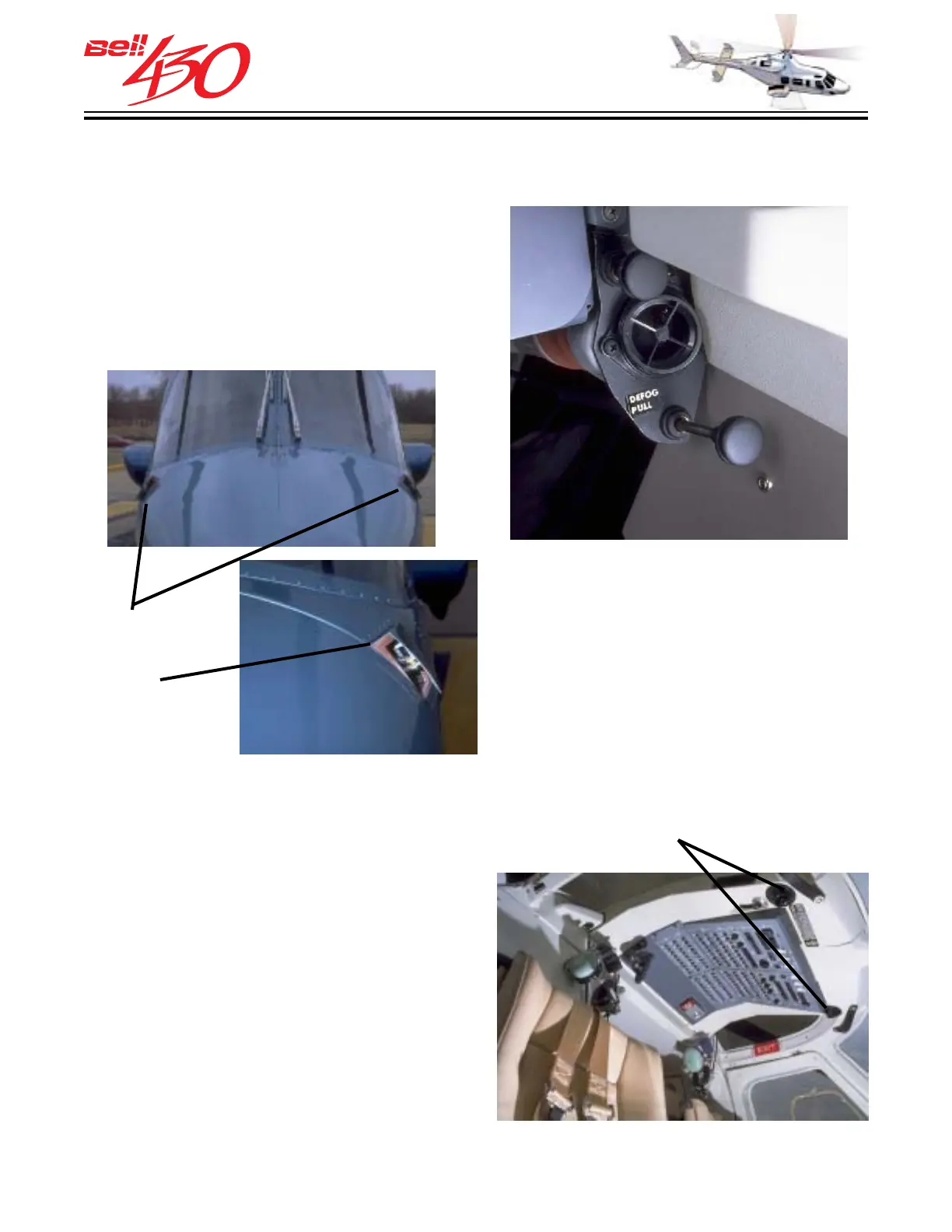
system consists of an exterior plenum door
(on one side of the nose), an electric blower,
diverter valve, ducting, check valve,
windshield defog nozzle, adjustable vent
nozzle, and two control cable assemblies.
LOWER CREW AIR OUTLET
LEFT & RIGHT
COCKPIT
AIR INLETS
[DETAIL]
UPPER CREW AIR OUTLETS