43
THIS IS AN UNCONTROLLED DOCUMENT.
THIS ELECTRONIC DOCUMENT MAY HAVE BEEN SUPERCEDED.
THE MOST CURRENT DOCUMENT INFORMATION IS AVAILABLE
FROM YOUR BELL HELICOPTER TEXTRON REPRESENTATIVE.
PRODUCT DATA JANUARY 2003
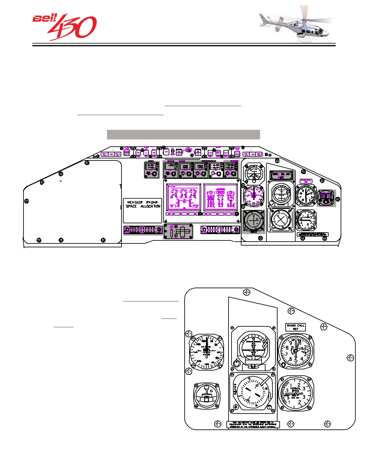
The standard instrument panel in the Bell 430 is fully equipped for VFR (Visual Flight
Rules) flight, day or night. It also has space to install additional communications and
navigation equipment, instruments and indicators necessary to conduct IFR/IMC
(Instrument Flight Rules/Instrument Meteorological Conditions) flight. The illustration
below shows the normal locations for
standard instruments, as well as space reserved
for selected factory installed options .
OVERALL INSTRUMENT PANEL LAYOUT
[SHOWN WITH OPTIONAL EQUIPMENT SHADED]
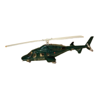
STANDARD ELECTROMECHANICAL PILOT INSTRUMENTS
Operating limitations are clearly indicated
on all electromechanical instruments, with
green, yellow, and red bands on the
face,
or the
bezel. The following instruments are
provided with the standard configuration.
RIGHT (PILOT) SECTION
INSTRUMENT PANEL LAYOUT
1
2
3
4
5
6
1. AIRSPEED
2. ATTITUDE INDICATOR
3. ALTIMETER
4. VERTICAL SPEED
5. HSI-[WITH COMPASS SYSTEM]
6. TURN AND SLIP
7. STANDBY MAGNETIC COMPASS
(STBY. COMP. NOT SHOWN-SEE NEXT PAGE)