143
THIS IS AN UNCONTROLLED DOCUMENT.
THIS ELECTRONIC DOCUMENT MAY HAVE BEEN SUPERCEDED.
THE MOST CURRENT DOCUMENT INFORMATION IS AVAILABLE
FROM YOUR BELL HELICOPTER TEXTRON REPRESENTATIVE.
PRODUCT DATA JANUARY 2003
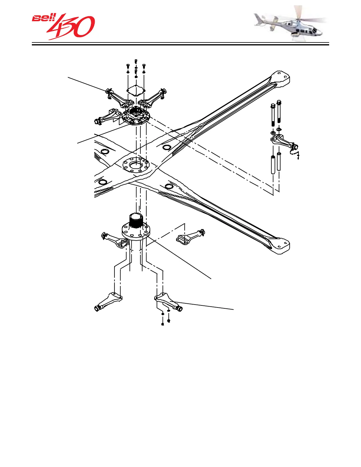
MAIN ROTOR HUB
The main rotor yoke is made of composite fiberglass materials. Its unique design allows
the yoke to take shear loads, bending loads (forward, rearward, up and down), and
twisting loads. There are no bearings used for feathering or flapping. This simple design
eliminates the need for lubrication. The two yoke flexures are mounted on top of each
other to form a stacked four bladed rotor system. The yokes are mounted directly to
the mast flange, with a dowel pin located on the flange to position the lower yoke. The
upper yoke will then mount 90° on top of the lower yoke. The drive plate assembly
mates with splines on top of the mast aligned with a match mark on the top of the mast.
A dowel pin located in the drive plate will align with a hole in the upper yoke to secure
the yoke alignment. Bolts passing through the mast flange and the drive plate will secure
the plates [and the up/down stops] to the mast flange.
MAIN ROTOR MAST FLANGE
DOWN STOPS
UP STOPS
DRIVE PLATE
ASSEMBLY