P1 Patient Monitor User’s Manual
8-20
When using 5-lead monitoring, the ST parameter area displays 7 ST
parameter values, namely ST-I, ST-II, ST-III, ST-aVR, ST-aVL,
ST-aVF and ST-V respectively.
When 6-lead monitoring is used, the ST parameter area shows the same
values of 8 ST parameters, namely ST-I, ST-II, ST-III, ST-aVR,
ST-aVL, ST-aVF, ST-Va and ST-Vb.
When 12-lead monitoring is used, the ST parameter area displays 12 ST
parameter values, namely ST-I, ST-II, ST-III, ST-aVR, ST-aVL,
ST-aVF, ST-V1, ST-V2, ST-V3, ST-V4, ST-V5, and ST-V6.
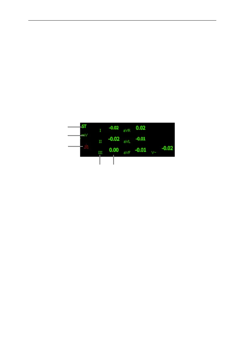
Take 5-lead as an example, the ST parameter area is shown as follows:
(1) Parameter label
(3) ST alarm off symbol
(2) ST unit
(4) Lead label
(5) ST numerics: a positive value indicates ST segment elevation, and a negative
value indicates ST segment depression.
8.7.4. Displaying ST Segment in Waveform Area
The steps for displaying ST segment in waveform area are as follows:
1. Enter the 【Screen Layout】 page in one of the following ways:
Select 【Screen Setup 】 quick keyselect 【 Screen Layout 】
submenu.
Select 【Main Menu】 quick keyfrom 【Display】 column to select
【Screen Layout】.
2. Click on the waveform area where you need to display ST segment, and select
【ECG】【ST Segment】 from the list.
1
2
4
5
3
 Loading...