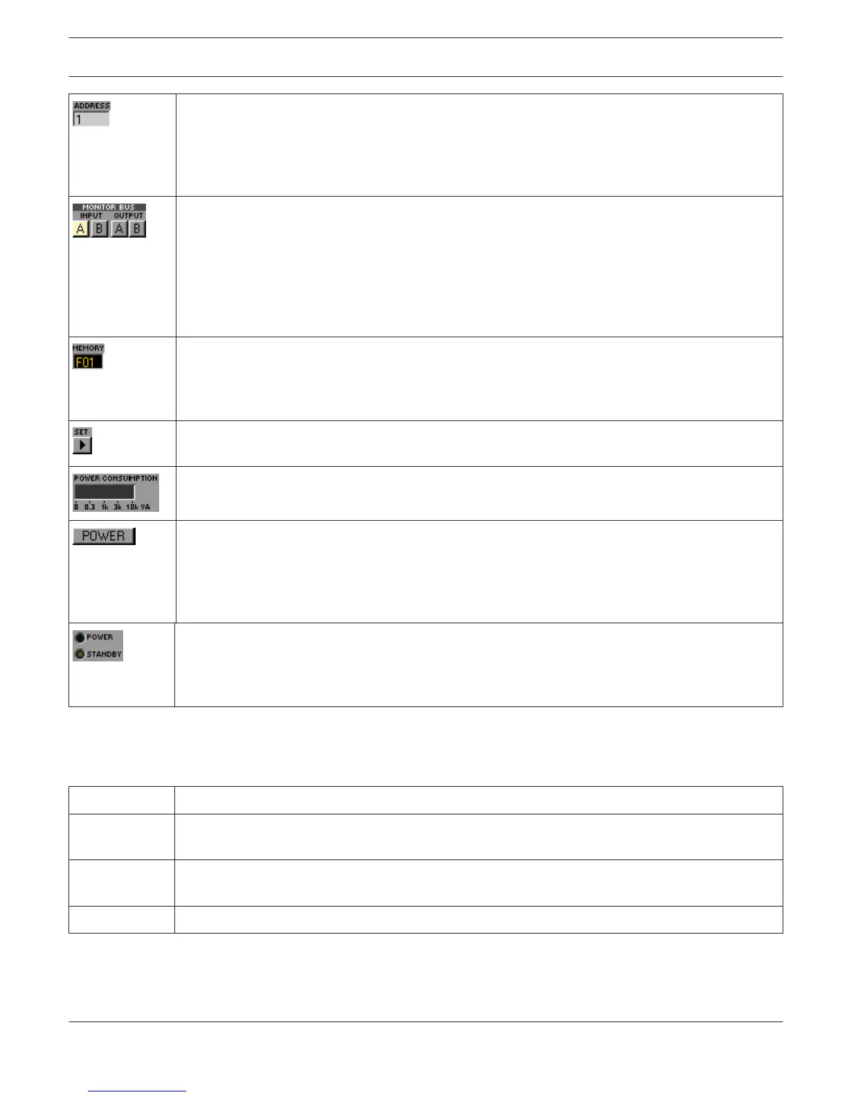
The address field indicates the set amplifier address. Assigning a new address is also possible by
clicking into the field with the left mouse but- ton and entering the desired amplifier address.
Available values are 1 to 250. Press Return on the computer keyboard to acknowledge your entry.
The assigned address and the address specified by the setting of the selection switch on the
amplifier’s rear panel have to be identical. Each address can exist only once within a system.
These buttons allow assigning amplifier channels to the monitor bus. The monitor bus allows
monitoring any amplifier input or output signals within an installation. INPUT A / B selects the
corresponding input signal while OUTPUT A / B allows switching between the output signals of
channels A and B. Simply click on an amp channel’s icon to select it for monitoring. The
corresponding channel is assigned to the monitor bus. Any previous selection is simultaneously
canceled, so that only the actually selected amp channel can be monitored. Clicking the button of
an active amp channel separates the channel from the monitor bus.
This field indicates the active factory, user or owner preset. Each remote amp has two factory
setting F01 (48 kHz) and F02 (96 kHz) offering linear settings and six user-programmable presets
U01...U06 for storing random user data. There are also two password-protected owner presets.
Loading and saving presets is done in the Setup & Control window.
Clicking on the SET button opens the Setup & Control Window, which provides access to all
amplifier- and DSP-parameters, control and monitoring functions plus additional function groups.
POWER CONSUMPTION indicates the current power consumption of the power amplifier in VA.
This soft-key allows switching an amplifier on or off. The STANDBY and POWER indicators signal the
actual operational status. The Config & Info window allows programming individual power-on delays
for each amplifier.
HINT: The power-on delay defaults to “Address*150ms”. For address 8 the power-on delay
default would be for example: 8*150ms=1200ms.
These indicators show the amp’s actual operational status.
STANDBY lights whenever the amplifier is in stand-by mode. POWER lights whenever the amplifier is
powered-on and ready for operation. If neither one of the indicators lights, the amplifier is either
off-line or powered-off.
Setup & Control
The Setup & Control window allows configuring all amplifier parameters. It also provides access to different test
functions. The window is divided into several pages according to the corresponding function groups:
Window Description
Config. & Info This page provides information about the amplifier and allows making several basic settings as well
as programming control functions.
DSP The DSP page provides an overview plus access to all DSP functions (Filter, Delay, X-Over, Limiters)
of the amplifier.
Speaker This page allows loading and displaying speaker data.
IRIS-Net REMOTE AMPLIFIER | en 181
Bosch Security Systems B.V. User Manual 2017.05 | 3.20 | F.01U.119.956