ShelvingEQ_Freq_Gain_02 Equalizer panel with label field for the RCM-24 Remote Amp.
Pre-set for band 5 of the channel equalizer. Equalizer type,
frequency, gain and BYPASS can be set. Possible
Connections: RCM- 24-Amp.
System_Supervision_01 The amplifier LED lights red when in Standby or Protection
mode. Otherwise, the LED lights green. The speaker LED
lights red at the occurrence of the load at the amplifier's
output going outside the range set by the minimum and
maximum impedance values (a open or shorted line).
Otherwise, the LED lights green. Possible Connections:
RCM-24-Amp.
RCM-26 User Controls
Following sets of connections are used in following table:
– RCM-26-Amp: TG-5, TG-7, H2500, H5000
– RCM-26-Amp-Channel: TG-5.ChA, TG-5.ChB, TG-7.ChA, TG-7.ChB, H2500.ChA, H2500.ChB, H5000.ChA, H5000.ChB
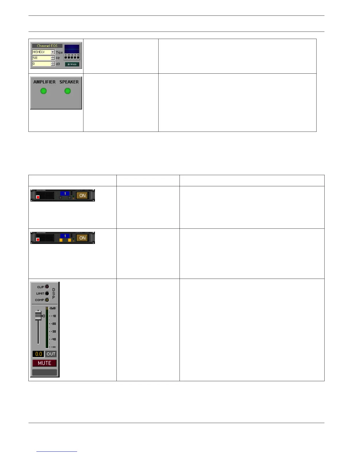
Picture Name Description
PowerH_Panel_01 In Online mode the LED light green. Otherwise, the LED
light red. The LEDs below the CAN address field light
green / yellow when the amplifiers is Power / Standby
mode. ON button for switching the amp's power on or
off. Possible Connections: RCM-26-Amp.
PowerH_Panel_02 In Online mode the LED light green. Otherwise, the LED
light red. The LEDs below the CAN address field light
green / yellow when the amplifiers is Power / Standby
mode. ON button for switching the amp's power on or
off. Additionally two LEDs for VU data of amplifier
inputs. Possible Connections: RCM-26-Amp.
RCM-26_Group_Panel_0
1
These three LEDs indicate clipping (CLIP) or whether
the limiter (LIMIT) or the compressor (COMP) of the
DSP is active. Fader and MUTE buttons for cont- rolling
and LED bar graph meter for monitoring the amp’s
output channel. Clicking onto the ”0” marking resets the
fader to 0 dB. Possible Connections: RCM-26-Amp-
Channel.
IRIS-Net IRIS-Net | en 28
Bosch Security Systems B.V. User Manual 2017.05 | 3.20 | F.01U.119.956