Level_Panel_
01
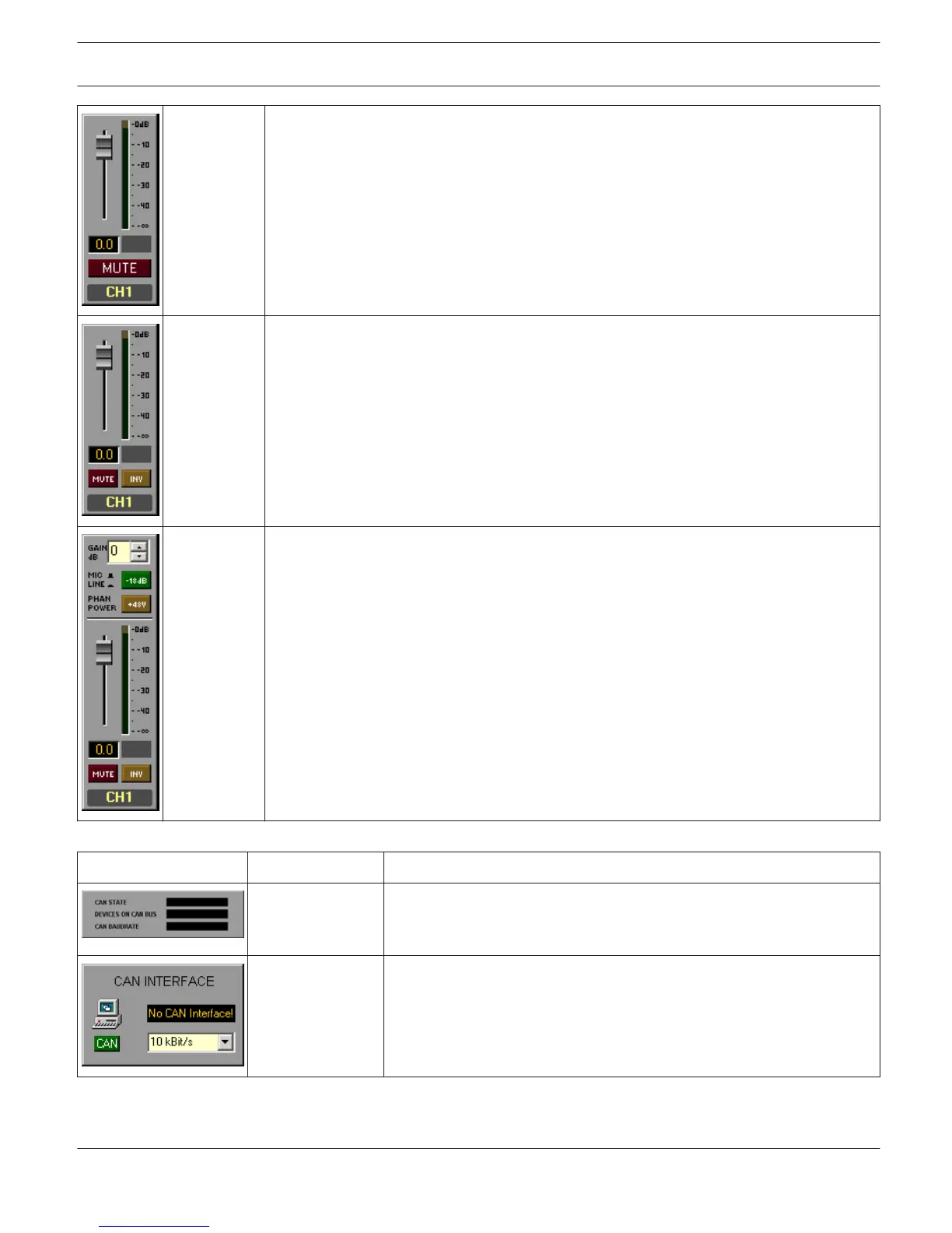
Fader and MUTE button for controlling and LED bar graph meter for monitoring a input/
output level. Possible Connections: N8000.DSP.AnalogIn.ChX,
N8000.DSP.AnalogMicIn.ChX, N8000.DSP.AnalogOut.ChX, N8000.DSP.AutoMixer.ChInX,
N8000.DSP.AutoMixer.ChOutX, N8000.DSP.DigitalIn.ChX
Level_Panel_
02
Fader, MUTE button and INV button for controlling and LED bar graph meter for
monitoring a input/output level. Possible Connections: N8000.DSP.AnalogIn.ChX,
N8000.DSP.AnalogMicIn.ChX, N8000.DSP.AnalogOut.ChX, N8000.DSP.AutoMixer.ChInX,
N8000.DSP.AutoMixer.ChOutX, N8000.DSP.DigitalIn.ChX
Level_Panel_
03
Fader, MUTE button and INV button for controlling and LED bar graph meter for
monitoring a microphone input level. Additionally Gain, MIC/LINE button and Phantom
Power button. Possible Connection: N8000.DSP.AnalogMicIn.ChX
Interface User Controls
Picture
Name Description
CAN_Interface_Sta
te_01
Shows the momentary state of the CAN bus, the amount of devices
connected to the bus and the cur- rent transfer rate. Possible
Connections: UCC1
CAN_Interface_Sta
te_02
Shows the momentary state of the CAN bus and the current transfer
rate. Use the CAN button to open the CAN Interface dialog. Possible
Connections: UCC1
IRIS-Net
IRIS-Net | en 36
Bosch Security Systems B.V. User Manual 2017.05 | 3.20 | F.01U.119.956