Measurem
ent
Generator
frequency,
Time, Level A /
B
Starts measurement with a tone signal of the specified frequency at
the levels specified for channels A / B for the selected duration (0 ms
= infinite)
Test
generator
Channel, Signal
type,
Frequency,
Solo/Pre, Level
Starts the test generator with selected signal type or of the specified
frequency at the levels specified for channels A / B for the selected
duration (0 ms = infinite)
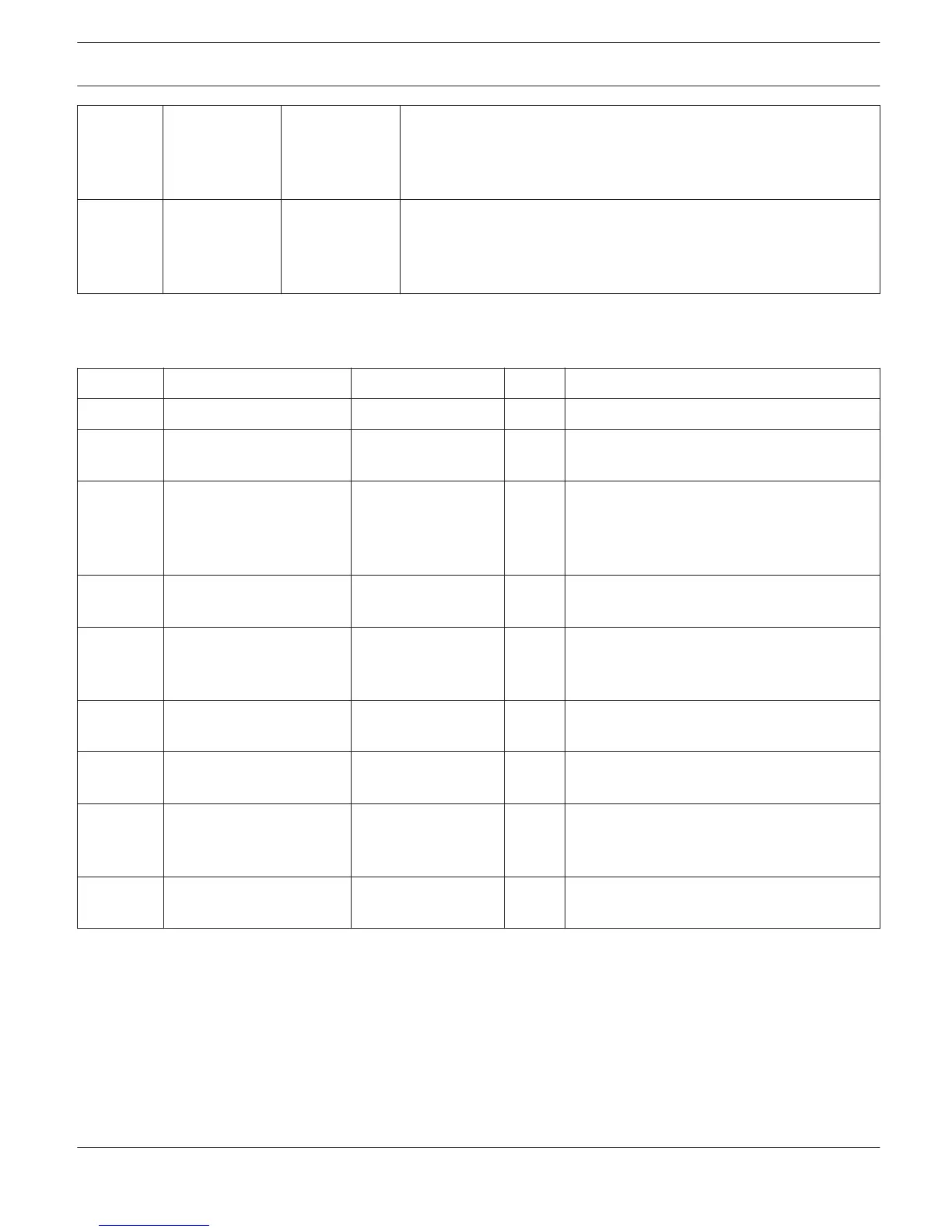
Output and Transmit Job Conditions: The following table lists all amplifier statuses that can be used for triggering
control outputs or for sending Transmit Job Codes.
Function
Parameter Opt.Value Invert Triggering Event/Status Change
Empty - - Not configured
Power
X
Power On
Power Off (Standby)
Absolute all DSP parameters Corresponding
Parameter Value
(parameter-
dependent)
X
Set parameter value reached or exceeded
Set parameter value declined
Temp Temperature in °C
X
Set temperature reached or exceeded Set
temperature declined
VU IN A, IN B, OUT A, OUT B,
Limiter A/B,
Compressor A/B
Level in dB
X
Set level reached or exceeded Set level
declined
GPI IN 1, IN 2
X
Control input 1 / 2 closed (ON) Control input
1 / 2 open (OFF)
Errorflag All internal fault
conditions
X
Single or several error flags set None of the
selected error flags set
Memoflag Enable for selected flags
as well as bit- pattern of
flags 1 - 16
X
Memory flags match the selected bit-pattern
Memory flags do not match the selected bit-
pattern
Preset U01 - U08, F01-F02, O01-
O02
X
Specified preset selected
Other than the specified preset selected
DSP
The DSP pages provide overview and access to all DSP parameters of an amplifier. Within this window you can use the
Flow Diagram Selector to link to different function groups.
FLOW DIAGRAM SELECTOR
The Flow Diagram Selector can be accessed from any DSP page offering navigation means within the DSP signal
processing functions. The Flow Diagram Selector lets you select different function blocks, where the actually selected
block is displayed in a yellow engaged field.
IRIS-Net REMOTE AMPLIFIER | en 189
Bosch Security Systems B.V. User Manual 2017.05 | 3.20 | F.01U.119.956