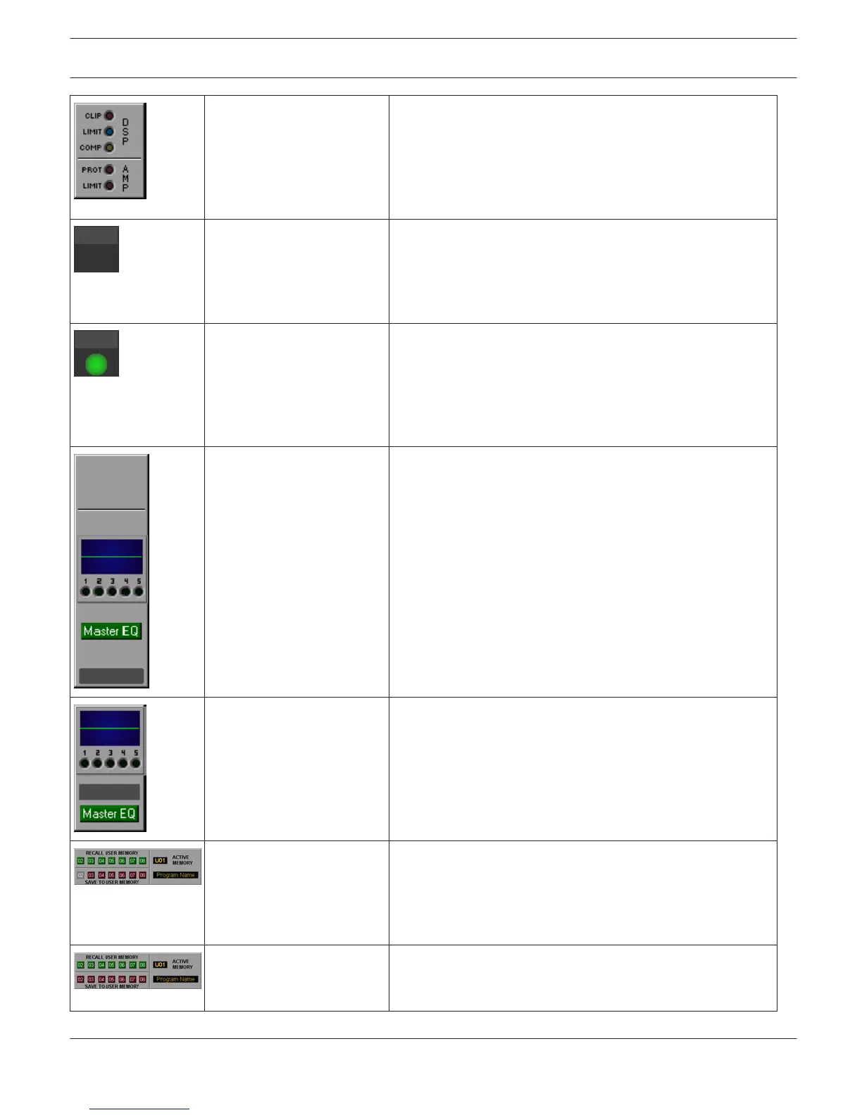
Group_LEDs_01 The three LEDs on the top indicate clipping (CLIP) or whether
the limiter (LIMIT) or the compressor (COMP) of the DSP is
active. The two LEDs on the bottom indicate that the unit
entered Protection (PROT) mode or that the amp’s limiter
(LIMIT) has been activated. Possible Connections: RCM-24-
Amp.
Labelled_LED_01 The LED lights red at the occurrence of the load at the
amplifier's output going outside the range set by the minimum
and maximum impedance values (a open or shorted line) or
when the unit is in Standby or Protection mode. Otherwise,
the LED is black. Possible Connections: RCM-24-Amp.
Labelled_LED_03 The LED lights red at the occurrence of the load at the
amplifier's output going outside the range set by the minimum
and maximum impedance values (a open or shorted line) or
when the unit is in Standby, Protection or MUTE mode.
Otherwise, the LED lights green. Possible Connections:
RCM-24-Amp.
Master_EQ_Panel_01 Equalizer panel with label field for the RCM-26 Remote Amp.
Use the Master EQ button to open the Master EQ dialog.
Possible Connections: RCM-24-Amp-Channel.
Master_EQ_Panel_02 Equalizer panel with label field for the RCM-26 Remote Amp.
Use the Master EQ button to open the Master EQ dialog.
Possible Connections: RCM-24-Amp-Channel.
Memory_Panel_01 Load user memory presets 2...8 or save to user memory
presets 3...8. Overwriting user memory preset 2 is not
possible. Number and name of the currently active user
memory is being indicated. Possible Connections: RCM-24-
Amp.
Memory_Panel_02 Load user memory presets 2...8 or save to user memory 2...8.
Number and name of the currently active user memory is
being indicated. Possible Connections: RCM-24-Amp.
IRIS-Net IRIS-Net | en 27
Bosch Security Systems B.V. User Manual 2017.05 | 3.20 | F.01U.119.956