This example shows the programming of two control outputs where OUT1 signals whether the amplifier’s power is
switched ON or OFF while OUT2 signals faulty operation.
– OUT1 ON: Power (control output 1 is closed when the amplifier’s power is switched on)
– OUT1 OFF: Invert Power (control output 1 is open when the amplifier’s power is switched off / stand-by mode)
– OUT2 ON: Errorflag (control output 2 is closed when operational faults according to the parameter list have
occurred)
– OUT2 OFF: Invert Errorflag (control output 2 is open when no faults have occurred)
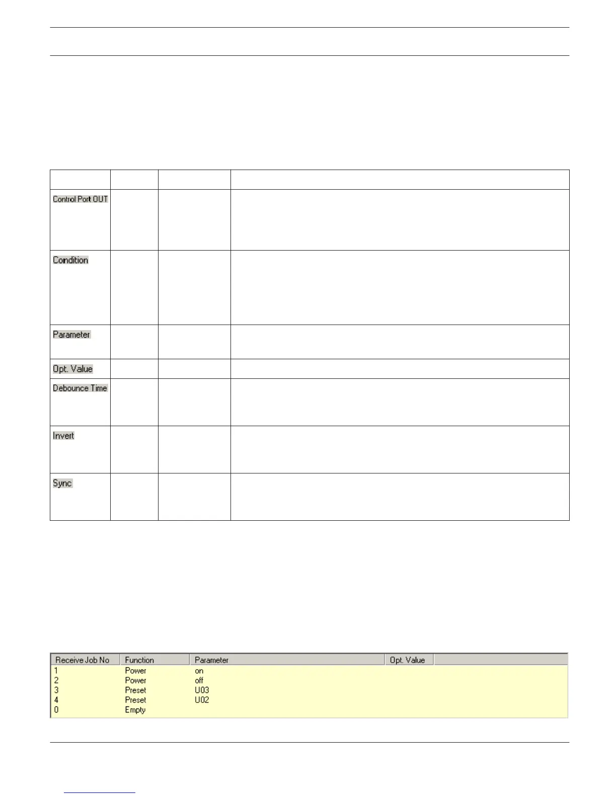
Element Default Range Description
0 OUT 1 ON
OUT 1 OFF
OUT 2 ON
OUT 2 OFF
This provides a listing of the two control outputs and their statuses ON and
OFF. The entries in the corresponding lines specify which status results in
the closing (ON) or opening (OFF) of a contact.
(empty) This column allows assigning internal events (conditions) to a control
output’s statuses. Clicking the desired line in the Function menu opens a
dialog field that shows all accessible functions. The table "Output and
Transmit Job Conditions" lists all functions together with their individual
set- tings.
(empty) Here you can set the different function parameters. For more information,
please refer to the table "Output and Transmit Job Conditions".
(empty) Certain functions allow specifying optional parameter values.
0 ms 0...10027 ms
16.33 ms
Steps
Here you can program delay or debouncing times. An event is signaled
following an internal status change and after the specified time interval has
past.
(empty) (empty) / X This column allows entering whether a status is signaled when the specified
Condition is „true“ (no entry) or „false“ (click „X“ to signal an inverted
state).
(empty) This column displays the SYNC flag. „X“ specifies that the output is
synchronized with a sync- signal. This flag is erased when entering a new
Function.
Jobs
For amplifiers to be able to communicate with each other, it is possible to send and receive Job Codes. In principle, a
job code is a function number that an amplifier transmits via CAN-bus and that is received and interpreted by another
or several other amplifiers. Each amplifier is capable of transmitting and receiving up to 5 different job codes.
Programming job codes is nearly identical to the programming of control inputs and outputs.
Receive Jobs: A receive job is a function that is carried out as soon as the corresponding function number (the Receive
Job Code) is received.
Example:
IRIS-Net
REMOTE AMPLIFIER | en 186
Bosch Security Systems B.V. User Manual 2017.05 | 3.20 | F.01U.119.956