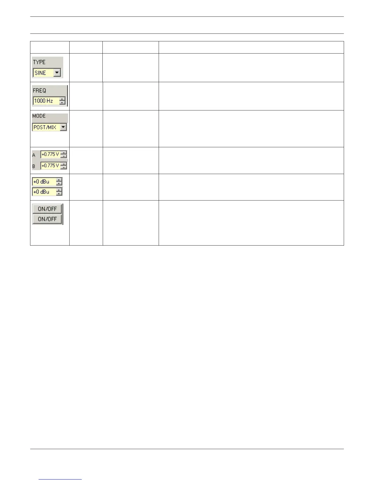
Element Default Range Description
SINE SINE, WHITE, PINK Type selects the test tone's signal-type. Available choices are: sine
signal, white noise or pink noise.
1000 Hz 20...20000 Hz Freq defines the frequency of the sine signal. This parameter is not
available when WHITE or PINK has been chosen as a test-tone signal.
PRE/SOLO POST/MIX, POST/
SOLO, PRE/MIX,
PRE/SOLO
MIX/SOLO determines whether the generated signal should be
mixed with an existing signal. PRE/POST determines if the signal
should be generated at the front (PRE) or the rear (POST) of the
signal processing chain.
0.775 V 0.001...2.451 V These controls are for setting output voltage [V] of the
corresponding amplifier outputs.
0 dBu -60...+10 dBu These controls are for setting output level [dBu] of the
corresponding amplifier outputs.
OFF OFF, ON These ON/OFF push-buttons activate or deactivate test-tone signal
output via corresponding amplifier channels.
CAUTION: Make sure to set a suitable output level, before
activating the generator. Extreme output levels can lead to
permanent damage of the connected loudspeaker systems!
Error Detection
Error detection lists the individual STATE of fault indications. Errors collected are amp failure, channel failure, cable
interruption, short-circuits, load deviation, ground fault, erroneous communication via the CAN bus as well as fault
messages of other amps. A green STATE indicator signals normal operation. A red STATE indicator signals error
detection.
If one of the corresponding DETECT boxes is marked, the state of that message is additionally included in the COLLEC-
TED ERROR STATE. When activating the HOLD option, the indicator stays red after the occurrence of an error. If the
HOLD option is not active, indication returns to green, once the fault is not detected anymore. Pressing the CLEAR but-
ton in the COLLECTED ERROR STATE line resets the indicator from red to green and stored errors are deleted. The
COLLECTED ERROR STATE indicator resembles exactly the Amplifier State indicator of the System Check Window. The
collected fault state message can be outputted via a control output. For detailed explanation please refer to chapter
Config & Info.
IRIS-Net
REMOTE AMPLIFIER | en 217
Bosch Security Systems B.V. User Manual 2017.05 | 3.20 | F.01U.119.956