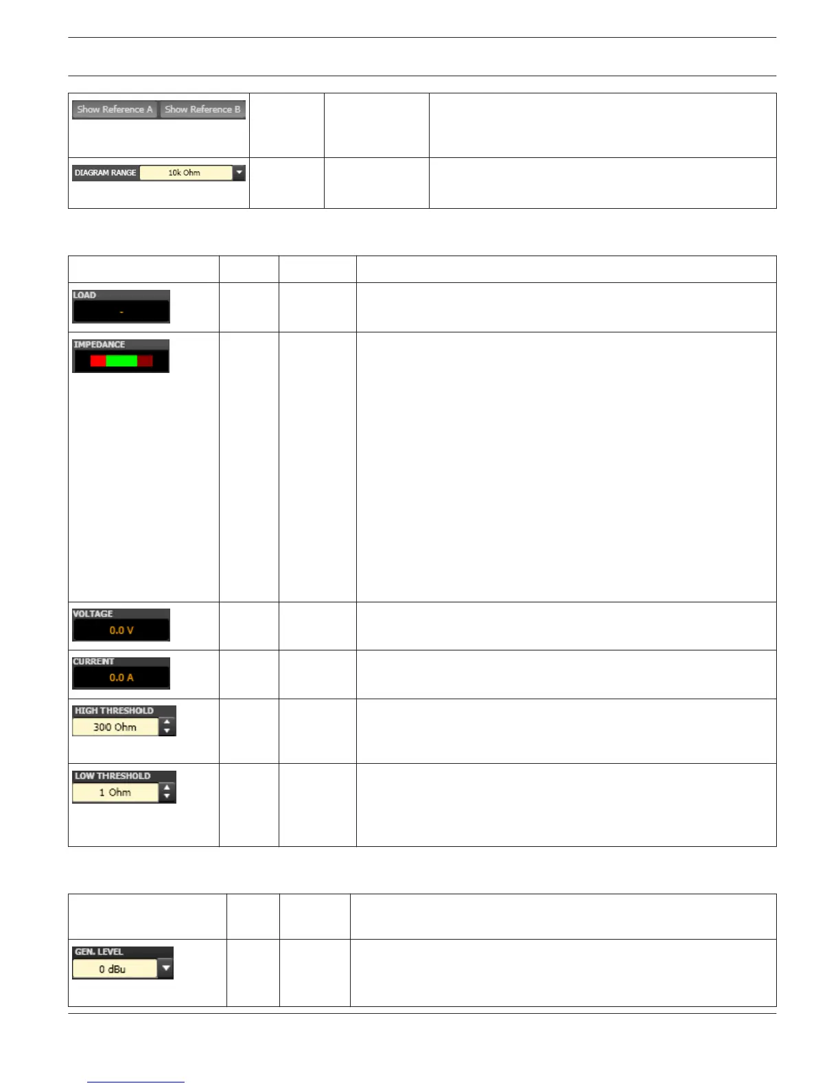
The switches "Show Reference A" and "Show Reference
B" turn the indication of the corresponding reference
impedance graphs ON or OFF.
10 kOhm 50 Ohm...10
kOhm
DIAGRAM RANGE allows zooming in or out the diagram’s
impedance range (Y- axis).
Parameters And Indications For The Continuous Monitoring Of The Load Connected
Element Default Range Description
The load display indicates the quotient of measured voltage and
current (U/I).
This indication shows the actual measured load, the progression, and
the set value range. The orange needle indicates the actual value.
The bright green bar indicates which loads have already been
measured while being on-line. A red indication signals that the value
exceeded or fell short of the set value range. The dark green area
represents the allowable value range for the load of the
corresponding power amp channel. The set HIGH THRESH
respectively LOW THRESH values define the limits for this value
range. Moving the cursor over the indication bar brings up a tool- tip
context menu showing the numerical value of the lowest, the
highest, and the actually measured load values. Clicking with the
right mouse button on the indication bar, followed by a click on
Reset, clears the previously measured load values (bright green and
red ranges disappear).
The VOLTAGE display provides continuous indication of the
corresponding power amp channel’s output voltage.
The CURRENT display provides continuous indication of the
corresponding power amp channel’s output current.
300
Ohm
0 Ohm...10
kOhm
HIGH THRESH sets the upper limit of the allowable impedance range
(= minimum load). Once this value is exceeded, an OPEN fault
message (line interrupt) appears in the Amplifier Control Panel.
1 0hm 0 Ohm...
300 Ohm
LOW THRESH sets the lower limit of the allowable impedance range
(= maximum load). Once this value is fallen short of, a SHORTED
fault message (line short- circuit) appears in the Amplifier Control
Panel.
Parameters For Impedance Measurement
Element
Defaul
t
Range Description
0 dBu -10 / 0 /
10 dBu
GEN. LEVEL sets the generator level for speaker impedance testing.
CAUTION: Extremely high levels during measurement may result in
seriously damaging connected components.
IRIS-Net REMOTE AMPLIFIER | en 282
Bosch Security Systems B.V. User Manual 2017.05 | 3.20 | F.01U.119.956