Graphics Display Indication
The graphics display offers several different indication modes, as described in the following table. Indication generally
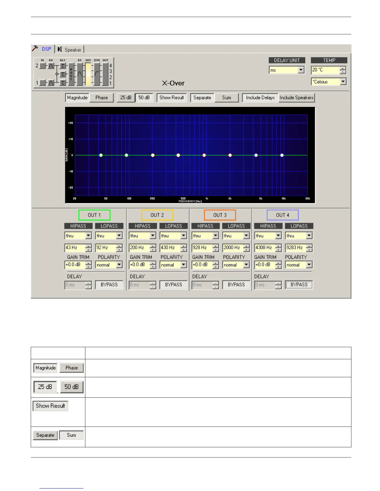
includes all effects of filters that are located pre X-Over (Master EQ, Channel EQ), which always provides precise over-
view and control of the resulting frequency response at this point.
Element Description
Switch for displaying frequency response (magnitude) or phase response (phase)
Switch for scaling the amplifier axis to 25 dB (± 12.5 dB) or to 50 dB (± 25 dB)
Displays the resulting transfer function of all filter and level trim settings and therefore the visible
respectively audible result at the sound system processor outputs. The audible result is displayed
in bright colors while all ”electrical” graphs are drawn in dark colors.
The ”Separate” switch allows separate indication of the two amplifier channels’ transfer
functions. The ”Sum” switch causes display of the summed signal of the two channels.
IRIS-Net DIGITAL SOUND PROCESSOR | en 595
Bosch Security Systems B.V. User Manual 2017.05 | 3.20 | F.01U.119.956