Switch for including programmed delays in the frequency or phase response indication. The delays
mainly affect phase response indication. Indicating the sound system processor channels’ summed
signals reveals very clearly the effect that the delays have on the frequency res- ponse, e.g. as notch
filter effect.
Switch for additionally indicating measured speaker transfer functions. For this function to be
effective you first have to load speaker data in the ”Speaker” tab.
Channel Selection
Element Description
Switch for selecting output 1, 2, 3, 4. 5 or output 6 for filter editing.
A click with the right mouse button opens the ”Copy & Paste” menu, which allows convenient copying all
X-Over settings of the corresponding output to any other X-Over within the same project.
Channel parameter
Element
Default Range Description
thru, 35 Hz RESPONSE:
thru, 6dB,
12dB/Q=0.5, 12dB/Q=0.6,
12dB/Q=0.7,
12dB/Q=0.8, 12dB/Q=1.0,
12dB/Q=1.2,
12dB/Q=1.5, 12dB/Q=2.0,
Bessel 12dB, Butterworth
12dB, Linkwitz/Riley 12dB,
Bessel 18dB, Butterworth
18dB, Bessel 24dB,
Butterworth 24dB, Linkwitz/
Riley 24dB
FREQ:
20 Hz to 20 kHz
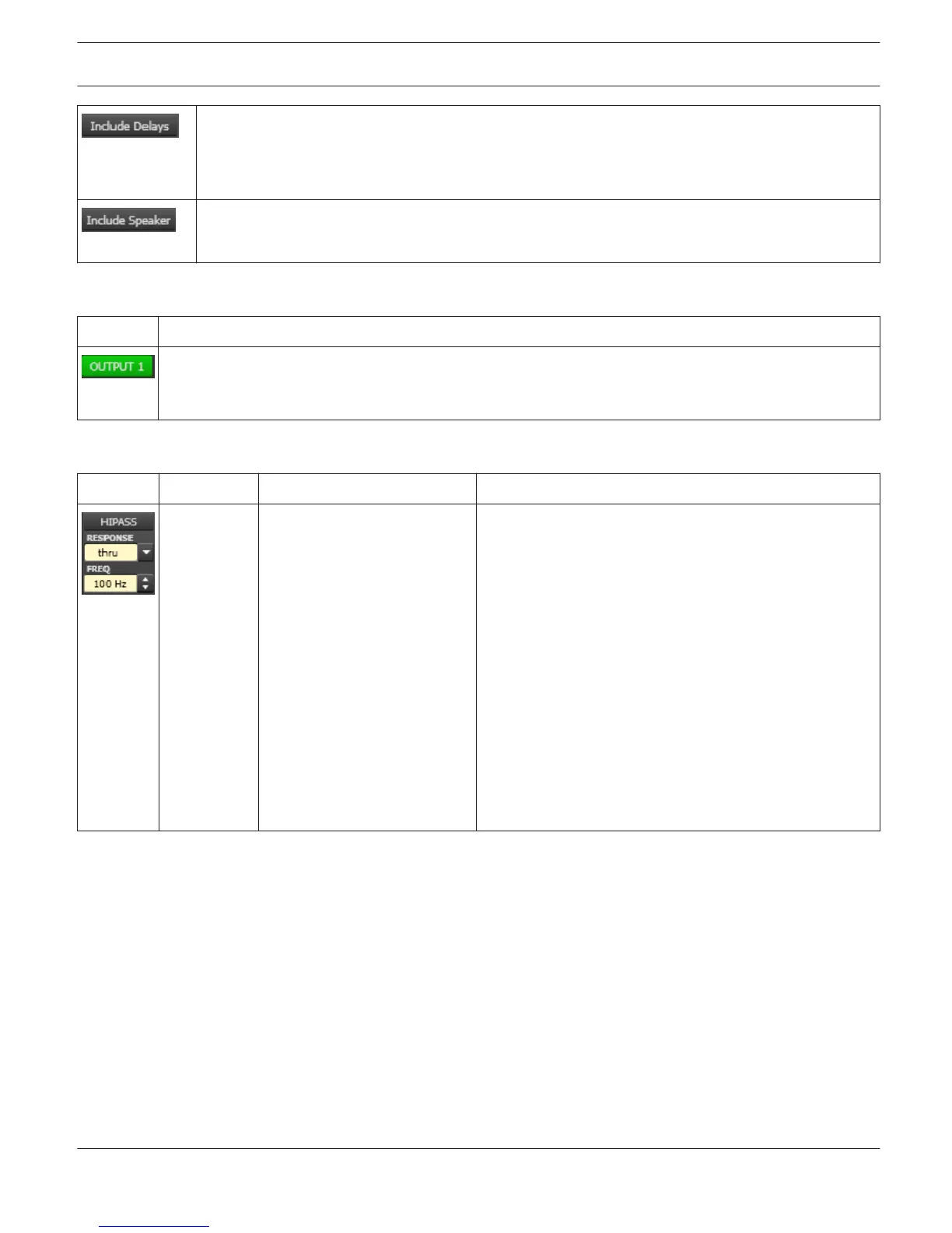
This parameter block represents the HI-PASS filter.
Different types of filters (Bessel, Butterworth, Linkwitz/
Riley) with slopes between 6 dB/Oct. and 24 dB/Oct. can
be set as filter response. Selecting filter frequencies
between 20 Hz and 20 kHz is possible as well.
A click with the right mouse button on the HIPASS field
opens the Copy & Paste menu, which allows copying all
parameters of the corresponding HI-PASS filter to any HI-
PASS filters within the same project.
IRIS-Net DIGITAL SOUND PROCESSOR | en 634
Bosch Security Systems B.V. User Manual 2017.05 | 3.20 | F.01U.119.956