interface between the PC and the CAN-bus. For more detailed information please refer to the UCC1 owner’s manual.
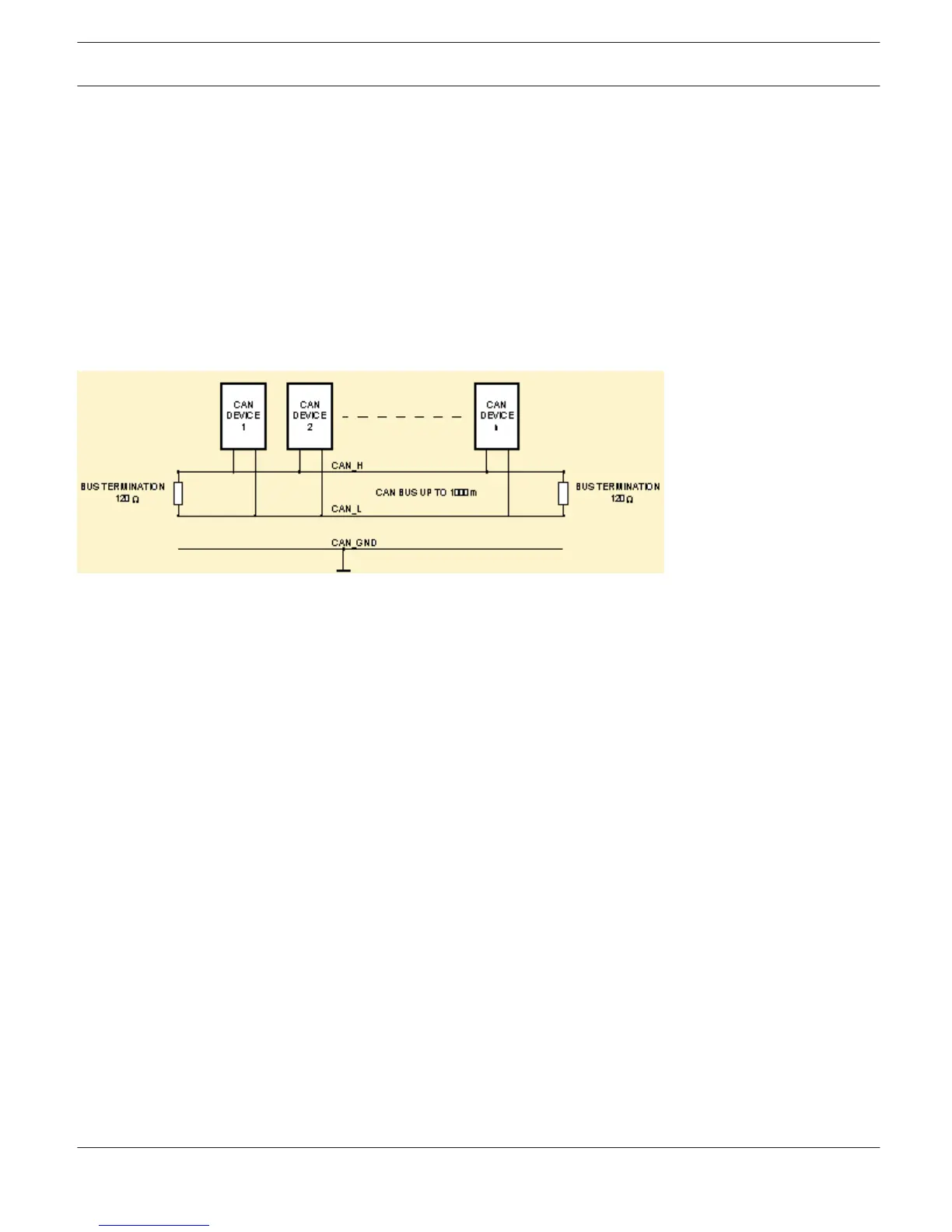
Up to 100 devices can be connected to a single CAN-Bus with a maximum total cable length of 1,000 metres. An
additional CAN-bus is needed for controlling more than 100 devices while the IRIS-Net software will support a total of
250 amplifiers. The network topology used by the CAN-bus is based on a “bus or line topology”, i.e. all participants are
connected via a single two-wire cable (Twisted-Pair cable, shielded or unshielded) with the cabling daisy-chained from
one participant on the bus to the next, allowing unlimited communication among all devices. In general, it does not
matter whether a participant on the bus is a power amplifier or a UCC1 USB-CAN converter, this flexibility allows a
UCC1 (and its associated PC) to be inserted at any position on the network. Incorporating several UCC1's on a single
CAN-bus is also possible. A total of up to 100 devices can be operated on a single CAN-bus. Since the CAN-interfaces of
all EV/DC devices are galvanically isolated from the rest of the circuitry, network cabling also carries a common ground
conductor (CAN_GND) ensuring that all CAN-interfaces in the network are connected to a common ground potential.
The UCC1 provides the possibility for switching the CAN-ground to circuit-ground.
Each participant on the bus system has two RJ-45 connectors for the Remote CAN-bus. These sockets are connected in
parallel to serve as input and output (for connecting through) for the data transfer within the remote-network. The
CAN-bus must be terminated at both ends using 120 Ω terminator plugs, two of which – CAN-TERM 120 Ω – are
supplied with the UCC1. Connect one of these to the RJ-45 socket of the first and the other to the socket of the last
appliance on the CAN-bus.
The following illustration shows an example of the data-bus wiring.
IRIS-Net
IRIS-Net | en 71
Bosch Security Systems B.V. User Manual 2017.05 | 3.20 | F.01U.119.956