Element Description
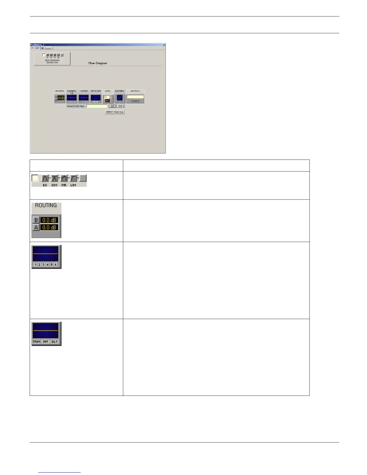
The flow diagram selector lets you select different function blocks,
where the actually selected block is displayed in a yellow engaged
field.
Here you can assign the output channel routing. The A and B buttons
allow selecting the input signal for the corresponding output channel.
Clicking with the right mouse button onto the dB display opens a
fader.
Channel EQ Block:
The Channel EQ block displays the 6 Channel EQs of the
corresponding output channel. The 6 LEDs indicate which EQ-bands
are being used while the graph shows the frequency response of the
Channel EQ block. A single click with the left mouse button onto this
block opens the CHANNEL EQ page. Clicking with the right mouse
button opens the Copy & Paste menu, which allows copying all
parameters of the corresponding EQ block to any other EQ block
within the same project.
Crossover Block:
This block represents the crossover within the corresponding output
channel. The graph shows the frequency response that results from
the set X-Over parameters. Three additional LEDs indicate the status
of gain trim, polarity and delay. A single click with the left mouse
button onto this block opens the X- OVER page.
Clicking with the right mouse button opens the Copy & Paste menu,
which allows copying all parameters of the corresponding X-Over
block to any other X-Over block within the same project.
IRIS-Net IRIS-Net | en 94
Bosch Security Systems B.V. User Manual 2017.05 | 3.20 | F.01U.119.956